
Roller cleaning system

A roller, clean technology, applied in furnace components, furnace types, furnace control devices, etc., can solve problems such as cumbersome economical angle and cumbersome time angle.

Inactive Publication Date: 2009-04-08
TECH CO TECNICA INT SPA
View PDF5 Cites 0 Cited by
  • Summary
  • Abstract
  • Description
  • Claims
  • Application Information

AI Technical Summary

Problems solved by technology

[0019] A disadvantage of this solution is that it is very cumbersome from an economic point of view
[0020] Another disadvantage of this solution is that it is very cumbersome in terms of the time required to replace the rollers

Method used


Image

  • Roller cleaning system
  • Roller cleaning system
  • Roller cleaning system

Examples


Embodiment Construction

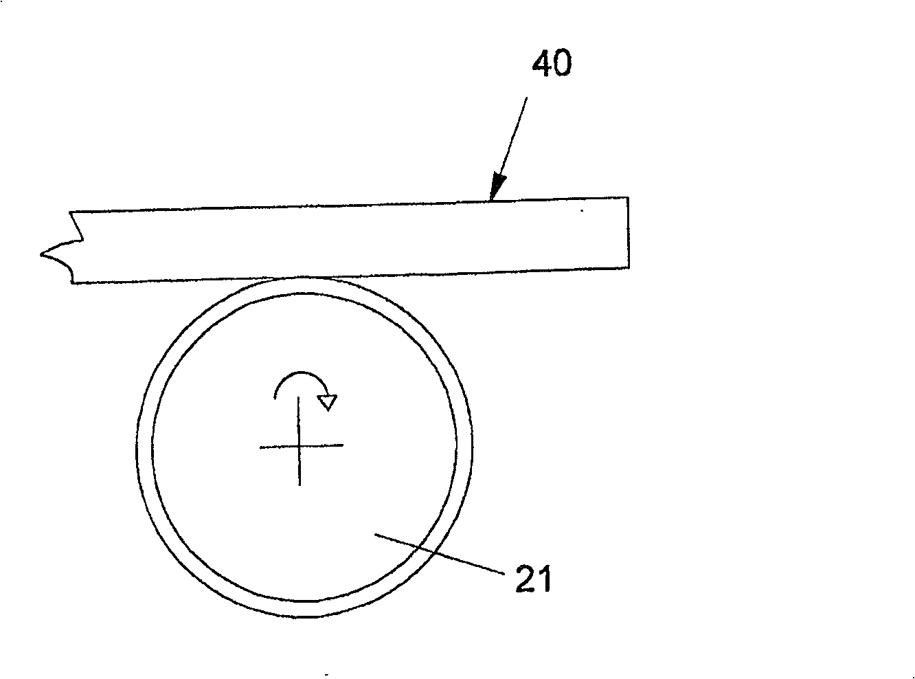
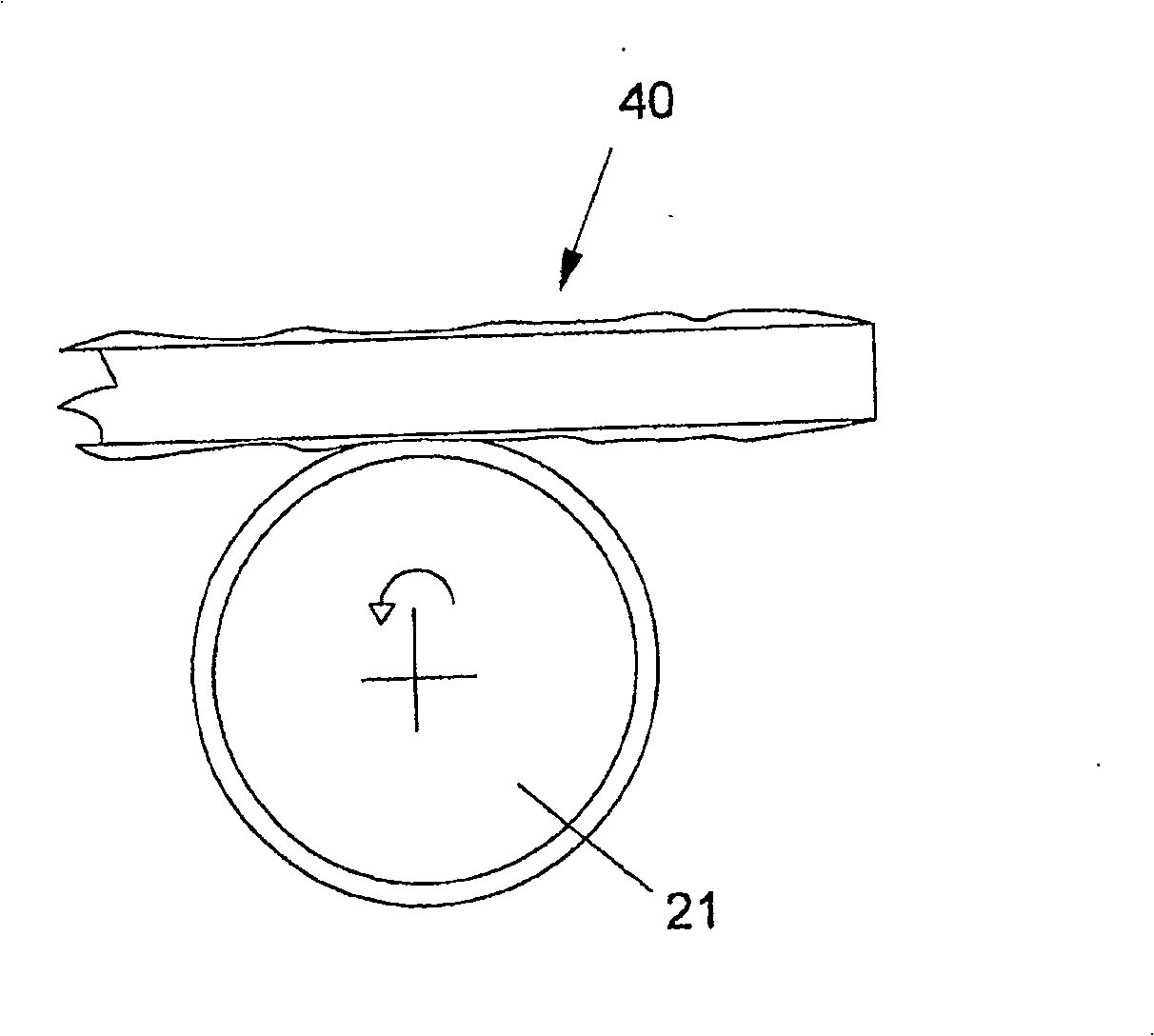
[0037] Referring to the accompanying drawings, with 10 indicating the whole of the roller cleaning system, in the embodiment shown, the roller cleaning system according to the invention comprises a control and regulation unit 14, which preferably communicates with Relevant control and excitation devices 26 are connected, such as PLC, and each relevant control and excitation device is connected with the motor 24 of each roller 21 through a frequency converter 25 (inverter), and the frequency converter controls the rotation speed of the motor 24 itself.

[0038] The cleaning system 10 is applied in a roller oven 20 equipped with a series of rollers 21 driven in rotation by individual motors 24 .

[0039] According to a preferred embodiment of the present invention, the roller cleaning system 10 is able to independently drive each mechanized roller of the series of rollers 21 through the control and regulation unit 14 and can be combined with other mechanized rollers of the series...


PUM


Abstract

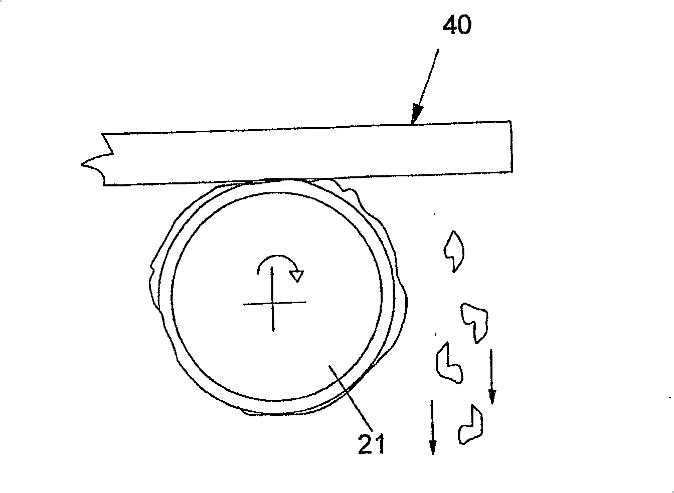
A roller cleaning system (10) for an oven (20) equipped with a series of motorized rollers (21) each of which is in turn connected to a relative motor-reducer (24) for rotation activation, in turn connected to a relative frequency converter (25) driven by a respective control and activation device (26), said roller cleaning system (10) comprising a control and regulation unit (14) to independently control the rotation rate and direction of each roller of the series of motorized rollers (21) for the advancing of one or more flat blooms (40) and for cleaning at least one roller (34) causing the detachment of the flakes of oxide therefrom by scraping it against a flat bloom (40) with a variation in the rotation rate and / or direction of the same.

Description

technical field [0001] The present invention relates to a roller cleaning system which can be used in particular to remove oxide flakes from the riders of the rollers of a heating oven for slabs or similar products to be laminated. Background technique [0002] In the steel industry, the use of direct lamination with finishing casting equipment and roller ovens has become more widespread when laminating flat rolled stock. [0003] These plants require an oven for the slab or similar product to be laminated, located directly downstream of the continuous casting, for transferring the slab or similar product to a rolling mill, which is designed to heat the slab itself Temperature optimization. [0004] The rolling mill is also located downstream of the oven. The physical transfer of the slabs into said oven is by means of a series of mechanized rollers, from which the term "roller oven" is derived. [0005] The roller oven also allows the slab to move and temporarily stay in...

Claims


Application Information

Patent Timeline
Patent Type & Authority Patents(China)
IPC IPC(8): F27D19/00F27D23/02F27B9/30F27B9/40B21B28/04C03B35/16B65G13/02B65G43/08F27B9/24F27B9/22F27D25/00
CPCF27D25/001F27B9/40F27B9/30F27D2019/0059F27D99/00F27B9/2407F27D19/00
Inventor E·菲利皮G·帕斯托里尼
Owner TECH CO TECNICA INT SPA
Learn More