
Real time photosurveying system and application thereof

A camera measurement and camera technology, applied in the field of real-time camera measurement systems, can solve the problems of complex equipment, inability of cameras to shoot synchronously, and inaccurate images.

Active Publication Date: 2009-05-13
北京尚水信息技术股份有限公司
View PDF4 Cites 0 Cited by
  • Summary
  • Abstract
  • Description
  • Claims
  • Application Information

AI Technical Summary

Problems solved by technology

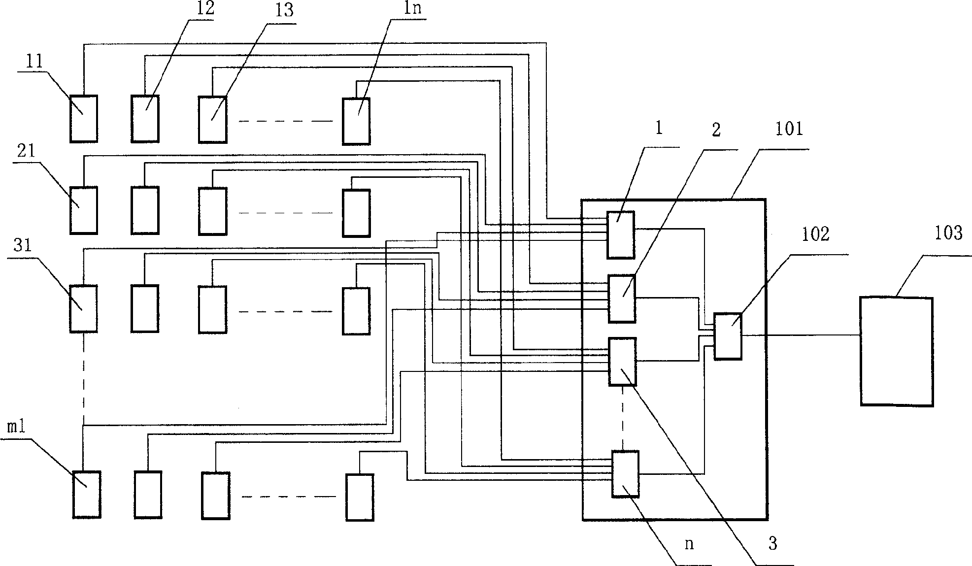
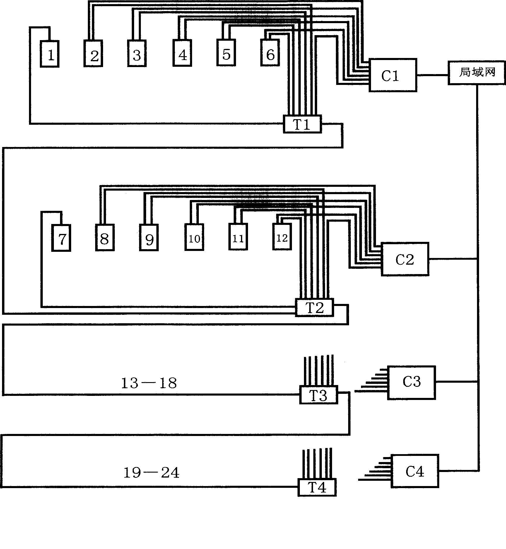
However, each camera in each of its subsystems cannot shoot synchronously. It collects the image of the second camera after collecting the image of the first camera, and so on. Although the interval is only 0.03-0.04 seconds, But for a large range of constant flow or non-steady flow velocity field, especially for the flow velocity field of non-steady flow, the accumulation of errors will lead to inaccurate images, and this patented technology uses local area network to realize the 1 in the figure The synchronization of camera No. 7 and camera No. 7, although this solves the synchronization problem, but in this patented technology, a subsystem needs to use a synchronizer and a computer, and a local area network is used between each subsystem to realize its internal synchronization , their synchronization is realized by means of a local area network, which not only has complex equipment, high error rate and high cost, but also increases the cost of network maintenance

Method used


Image

  • Real time photosurveying system and application thereof
  • Real time photosurveying system and application thereof
  • Real time photosurveying system and application thereof

Examples


Embodiment 1

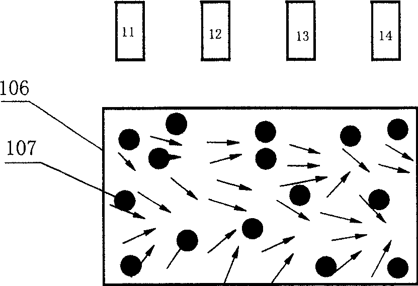
[0045] Fig. 3 (a) is the schematic diagram that the real-time camera measurement system of the present invention is used for velocity field; For the flow velocity field of flow or non-constant flow, select the number of camera groups according to the size of the model. The CCD camera in this example is composed of four groups of cameras, and each group of four cameras is selected, and each CCD camera of each group of CCD cameras is placed separately In different parts of the large-scale constant flow or non-constant flow field 106, the tracer particles 107 in the flow field 106 are monitored. According to the above-mentioned measurement method, the same Time and flow velocity fields at different times.

[0046] As can be seen from Fig. 3 (b), using the real-time video camera measurement system of the present invention to measure the flow velocity field of a wide range of constant flow or unsteady flow can draw the flow velocity fields of different parts at the same moment and ...

Embodiment 2

[0048] Figure 5 It is a schematic diagram of the real-time camera measurement system of the present invention being used for ship model navigation measurement; the ship model 104 in the navigation is measured with this system, and the CCD camera is made up of a group of two cameras, and the tracer 105 on the ship model 104 is placed on the ship model 104. Before and after the hull of the model 104, cameras are respectively placed on the front and rear of the ship model 104 above the route and correspond to the tracer 105 on the ship model, and the tracer 105 on the ship model 104 is monitored to obtain the ship model 104. The moving images of the hull of different parts of the model 104 at the same time and at different times.

Embodiment 3

[0050] Figure 6 It is a schematic diagram of the real-time video camera measurement system of the present invention being used for hull vibration measurement; the ship model 104 in the navigation is measured with this system, and the tracer 105 on the ship model 104 is placed on the front or rear of the ship model 104, up or down and On the left or right three positions ( Figure 6 Only one of them has been drawn), the CCD camera is made up of a group of three cameras, and each CCD camera is placed corresponding to the tracer 105 on the ship model 104 respectively, and the tracer 105 on the ship model 104 Monitoring is carried out to obtain images of the shaking and swaying of the hull of different parts of the ship model 104 at the same time and at different times.

[0051] In this example, the tracer 105 on the ship model 104 can also be placed on six positions of the front, back, up, down, left and right of the ship model, and the CCD camera is composed of a group of six ...


PUM


Abstract

The invention relates to the real-time camera measuring system and its application. The system comprises a group or groups of CCD cameras, the image collecting cards connecting to each CCD camera, a computer connecting the image collecting card. The said image collecting card comprises two or above data collecting cards and a data control card. Each group of the said CCD camera includes at least two or above cameras; every CCD camera connects the corresponding circuit of the input end of each data collecting card; the output end of each data collecting card connects the input end of the data control card; the output end of the data control card connects the input of the computer; the maximum number of each CCD camera group is equal to the data collecting card number; the group number of the CCD camera is equal to the circuit number of the data collecting card. The invention is applied to the measuring the invariable or variable velocity fields.

Description

technical field [0001] The invention relates to a real-time camera measurement system and its application, in particular to a real-time camera measurement system for measuring water velocity models or ship models, which is applied to measure the velocity field of a large range of constant flow or non-steady flow And measure the ship model under voyage. Background technique [0002] In the existing model tests of river engineering, harbor engineering and hydraulic engineering, there are roughly three types of measurement methods for water velocity: [0003] One is to use buoy tracers to manually time or take photos for post-processing. This method is time-consuming and laborious and has low accuracy, and is only suitable for approximate measurement of single-point flow velocity. [0004] The second is to use the commonly used instruments for the sink test. For example, the propeller current meter has improved measurement accuracy compared with the manual timing method of bu...

Claims


Application Information

Patent Timeline
Patent Type & Authority Patents(China)
IPC IPC(8): G01C11/00G01P5/20
Inventor 曲兆松
Owner 北京尚水信息技术股份有限公司
Learn More