
Exposure worktable and exposure device

A workbench and loading technology, which is applied in the direction of photolithography exposure device, microlithography exposure equipment, electrical components, etc., can solve the problem of local vacuum adsorption and keep on the exposure workbench, and achieve high-precision positioning operation and exposure Effects of homework, smooth motion, maintaining positioning accuracy and exposure accuracy

Active Publication Date: 2009-05-13
ORC MFG
View PDF7 Cites 0 Cited by
  • Summary
  • Abstract
  • Description
  • Claims
  • Application Information

AI Technical Summary

Problems solved by technology

[0015] In addition, in an exposure apparatus having an exposure stage, a series of operations including loading, positioning, exposure, and unloading are continuously performed. However, if the substrate cannot be properly vacuum-adsorbed and held on the exposure stage, the Unnecessary work such as temporarily stopping the device to remove the substrate may occur

Method used


Image

  • Exposure worktable and exposure device
  • Exposure worktable and exposure device
  • Exposure worktable and exposure device

Examples


Embodiment approach

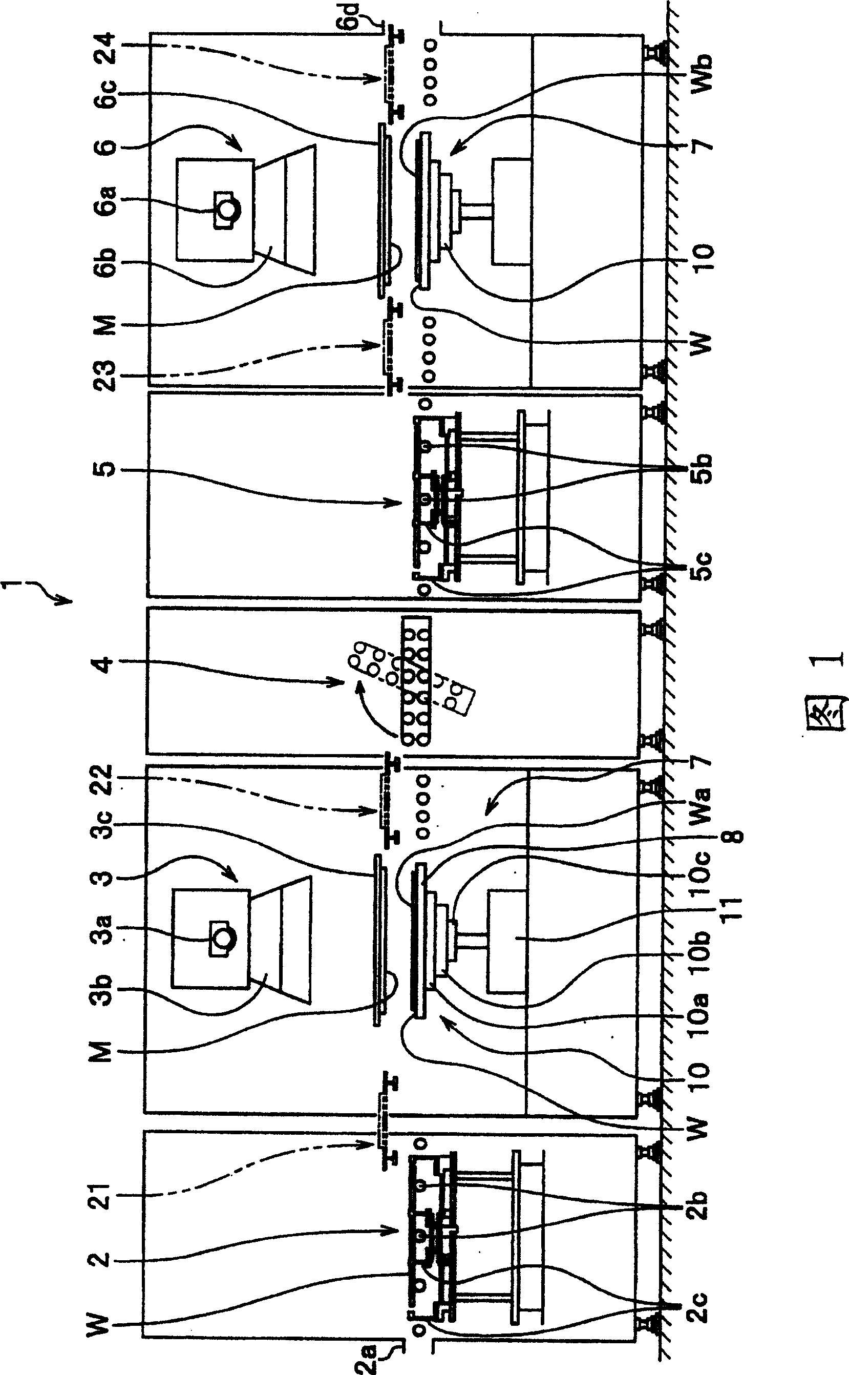
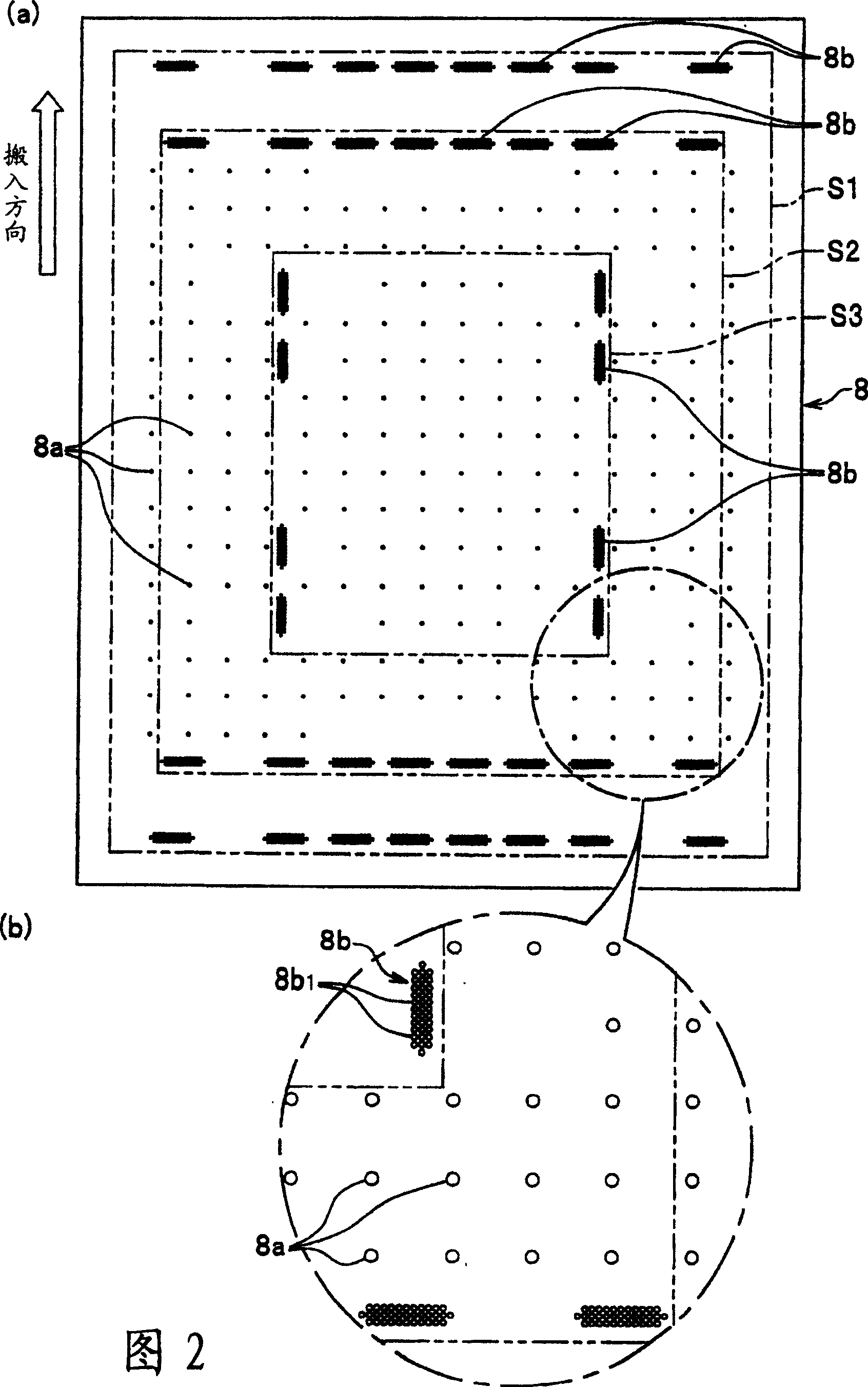
[0045] Hereinafter, best embodiments of an exposure stage and an exposure apparatus for carrying out the present invention will be described with reference to the drawings. In addition, although the exposure apparatus is demonstrated here as an example of the double-sided exposure apparatus which exposes the front surface and the back surface of a board|substrate, of course, it may be the exposure apparatus which exposes one side of a board|substrate. FIG. 1 is a schematic diagram schematically showing the entire exposure apparatus from the side, and FIG. 2 is a plan view of an exposure stage.

[0046] As shown in Figure 1, the exposure device 1 is a device for exposing the surface and the back surface of the substrate W, which includes: a placement mechanism 2 for pre-positioning the substrate W; a surface exposure mechanism 3, which is connected with the placement mechanism 2 adjacently arranged for exposing the surface Wa of the substrate W; an inverting mechanism 4 arrange...


PUM

PropertyMeasurementUnit
thicknessaaaaaaaaaa
thicknessaaaaaaaaaa

Abstract

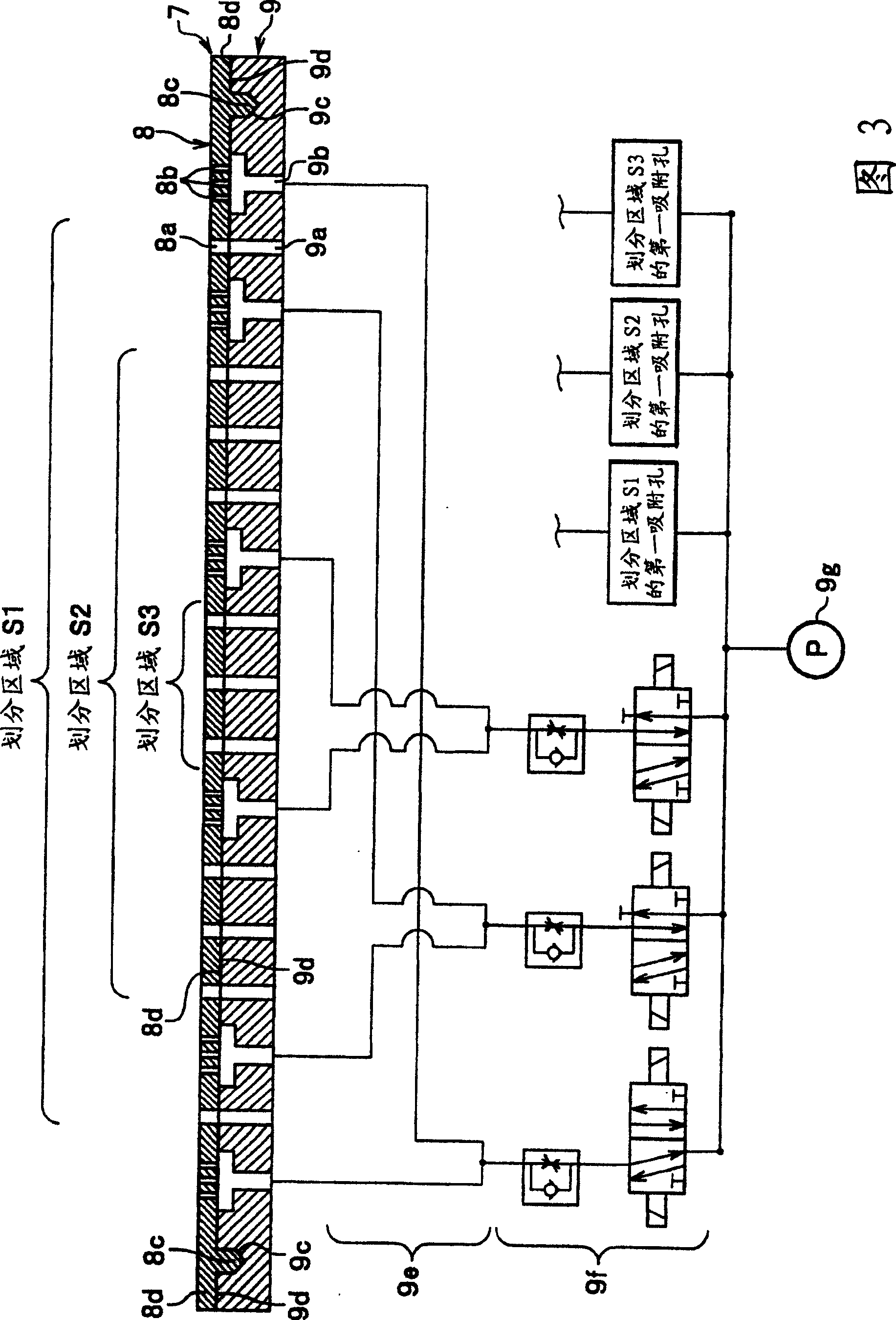
To provide an exposure table which can suitably hold by suction even a thin substrate and can hold a substrate even in a state where a substrate peripheral edge is waving, and is superior in maintenance operability for replacement etc of the table, by simple constitution even when a mount surface of the table for the substrate wears and so on due to the use of the table, and an exposure device which makes a series of operations smooth and improves the quality of the substrate. The exposure table 7 has a mount plate 8 for a substrate, a table main body 9 which supports the mount plate, a plurality of suction holes provided in the mount plate, and a communication path which is formed in the table main body and communicates with the suction openings. The suction holes include first suction holes 8a and second suction holes 8b which are formed as holes 8b1 smaller than the first suction holes, the suction holes are also arranged adjacent to one another to form suction hole groups disposed at predetermined positions at designated intervals along at least one of the longitudinal and lateral sides of the peripheral edges of the substrate.

Description

technical field [0001] The present invention relates to an exposure stage and an exposure apparatus on which substrates such as printed circuit boards are placed during exposure, and particularly relates to an exposure stage and an exposure apparatus that can appropriately cope with thin substrates. Background technique [0002] In general, substrates such as printed circuit boards have become extremely thin with the spread of thin and short electronic devices such as mobile phones and small computers. In addition, when forming a pattern on a thin substrate, since the strength of the peripheral edge is particularly low, the overall planarity is often impaired. Therefore, in the process of patterning the surface of the substrate, such as exposing the substrate, it is necessary to consider how to stably fix the substrate peripheral edge of the substrate fixing method. [0003] On the other hand, exposure devices for substrates are roughly classified into automatic exposure de...

Claims


Application Information

Patent Timeline
Patent Type & Authority Patents(China)
IPC IPC(8): G03F7/20H05K3/00
Inventor 伊势胜水口信一郎
Owner ORC MFG
Learn More