Diamagnetic rotor electromagnetic induction driving micro-gyroscope

A technology of electromagnetic induction and miniature gyroscope, which is applied in the direction of rotating gyroscope, gyroscope/steering induction equipment, and acceleration measurement using gyroscope, which can solve the problems of complex structure and process, and achieve the effect of simple process

Inactive Publication Date: 2009-05-20
SHANGHAI JIAOTONG UNIV
View PDF6 Cites 0 Cited by
  • Summary
  • Abstract
  • Description
  • Claims
  • Application Information

AI Technical Summary

Problems solved by technology

Its shortcoming is: by separating the suspension, stabilization and rotation coils, although the structure of the micro-gyroscope of the magnetic levitation rotor proposed earlier by C.Shearwood of the University of Sheffield in the United Kingdom and C. While rotating the coil, it is also necessary to provide suspension and stabilization coils respectively, and the structure and process are relatively complicated

Method used


Image

  • Diamagnetic rotor electromagnetic induction driving micro-gyroscope
  • Diamagnetic rotor electromagnetic induction driving micro-gyroscope
  • Diamagnetic rotor electromagnetic induction driving micro-gyroscope

Examples


Embodiment Construction

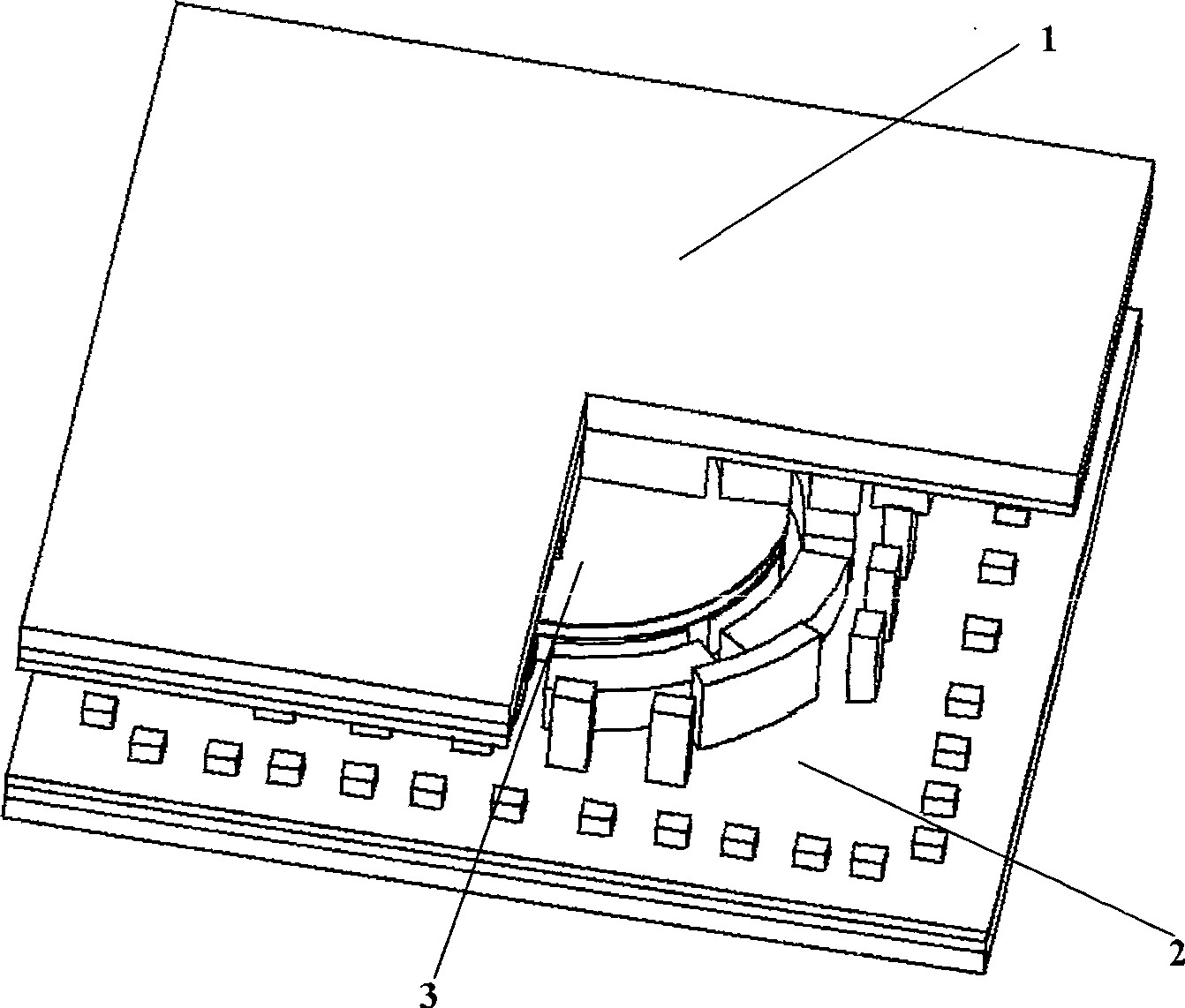
[0021] Such as figure 1 , what the present invention adopts is three-layer structure, is made of upper stator 1, rotor 3 and lower stator 2. The upper stator 1 and the lower stator 2 are electrically and mechanically connected by bonding, and form a cavity, and the rotor 3 is placed in the cavity.

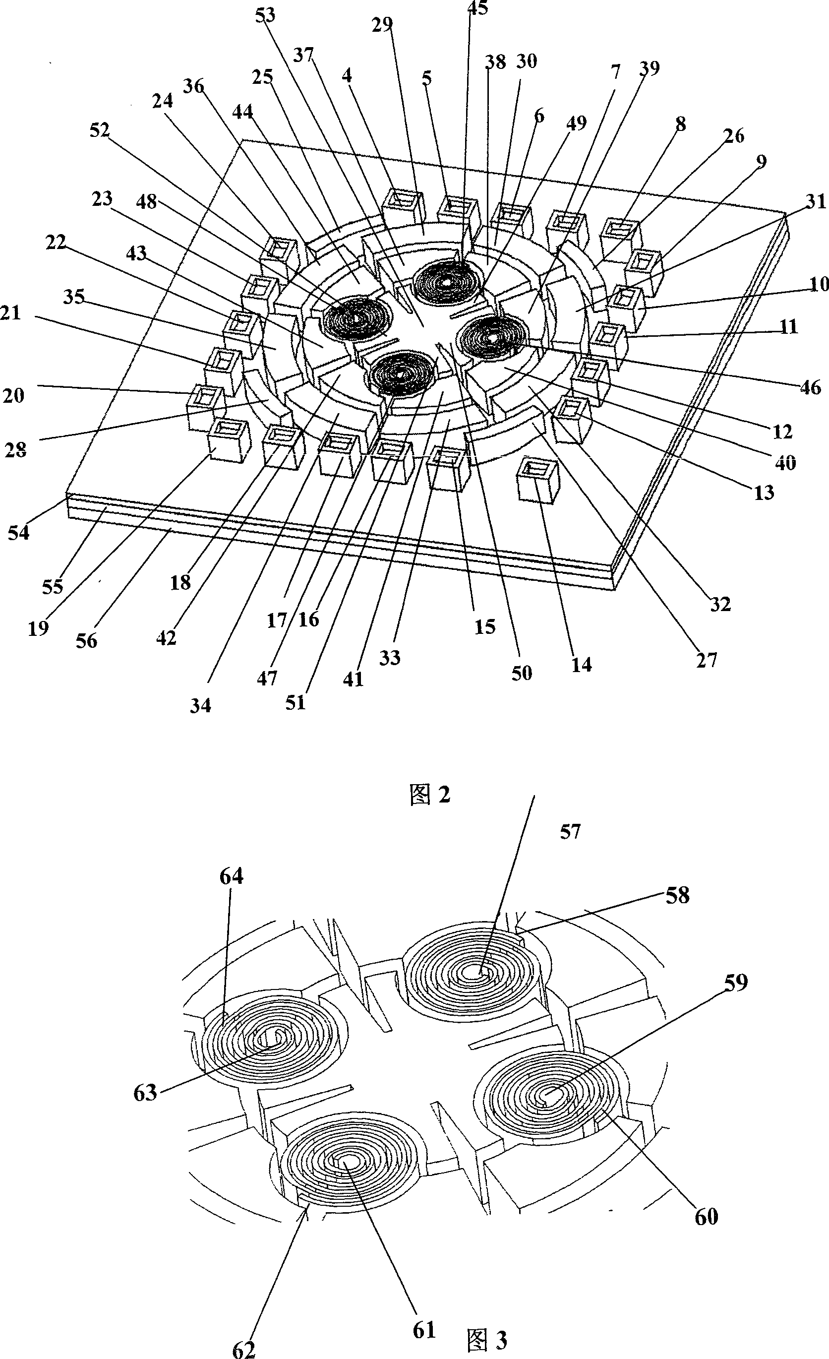
[0022]As shown in Figure 2, the upper stator 1 includes: the first upper right electrical conduction groove 4, the second upper right electrical conduction groove 5, the third upper right electrical conduction groove 6, and the fourth upper right electrical conduction groove Groove 7, No. 5 electrical conduction groove 8 on the upper right, No. 1 electrical conduction groove 9 on the lower right, No. 2 electrical conduction groove 10 on the lower right, No. 3 electrical conduction groove 11 on the lower right, No. 4 electrical conduction groove 12 from the lower right, No. 5 electrical conduction recess 13 from the lower right, No. 1 electrical conduction recess 14 from the lower ...


PUM


Abstract

A reverse magnetic suspension rotor electromagnetic induction driving micro gyro belongs to micro-electromechanical technology field. The invention is composed of an upper stator, a rotor and a lower stator. It takes upper and lower stators rotating capacity polar plates to drive variable-capacitance electrostatic rotating. Charging magnetism to four edge curve sections of public capacity polar plate construction composed of upper and lower stators which are made of permanent-magnet materials and capacity polar plates of upper and lower stators to detect z axle linear acceleration and wind x, y axles angular acceleration. Utilize diamagnetic materials to make rotor chip. Provide a reverse magnetic suspension rotor electromagnetic induction driving micro gyro adopting combination of permanent-magnet and diamagnetic materials to realize self-stabilization suspension, which leaves out suspension and stable coils. It can detects x, y, z axles linear acceleration and x, y axles angular acceleration simultaneously, which can realize precision positioning of objects, detect outside acceleration signal or navigate.

Description

technical field [0001] The invention relates to a miniature gyroscope in the field of micro-electromechanical technology, in particular to a miniature gyroscope driven by electromagnetic induction of a diamagnetic rotor. Background technique [0002] As we all know, the inertial navigation system has been widely used in the fields of aviation, spaceflight, navigation, and civil automobile industry due to its unique advantages. As an inertial device, micro gyroscope is one of the important MEMS devices. Compared with the traditional vibrating micro-mechanical gyroscope, the detection mass is separated from the substrate by levitating by electrostatic force (or electromagnetic force), and the development of a micro-gyroscope with a free-floating rotor is expected to improve the performance accuracy of the vibrating micro-mechanical gyroscope and reduce the driving vibration. The mechanical coupling quadrature error problem between the detection vibration and the detection vib...

Claims


Application Information

Patent Timeline
Patent Type & Authority Patents(China)
IPC IPC(8): G01C19/00G01P15/14G01C19/02G01C19/24G01P15/18
Inventor 张卫平张忠榕陈文元刘武
Owner SHANGHAI JIAOTONG UNIV
Why Eureka
Try Eureka