

Air inlet structure of reciprocating compressor
A technology of air intake structure and compressor, which is applied in the direction of liquid variable capacity machinery, mechanical equipment, variable capacity pump components, etc., can solve the problems of reduced refrigerant volume, increased refrigerant temperature, and decreased compressor efficiency, and achieves increased refrigeration. ability, the effect of increasing the amount of working fluid
- Summary
- Abstract
- Description
- Claims
- Application Information
AI Technical Summary
Problems solved by technology
Method used
Image


Examples
Embodiment Construction
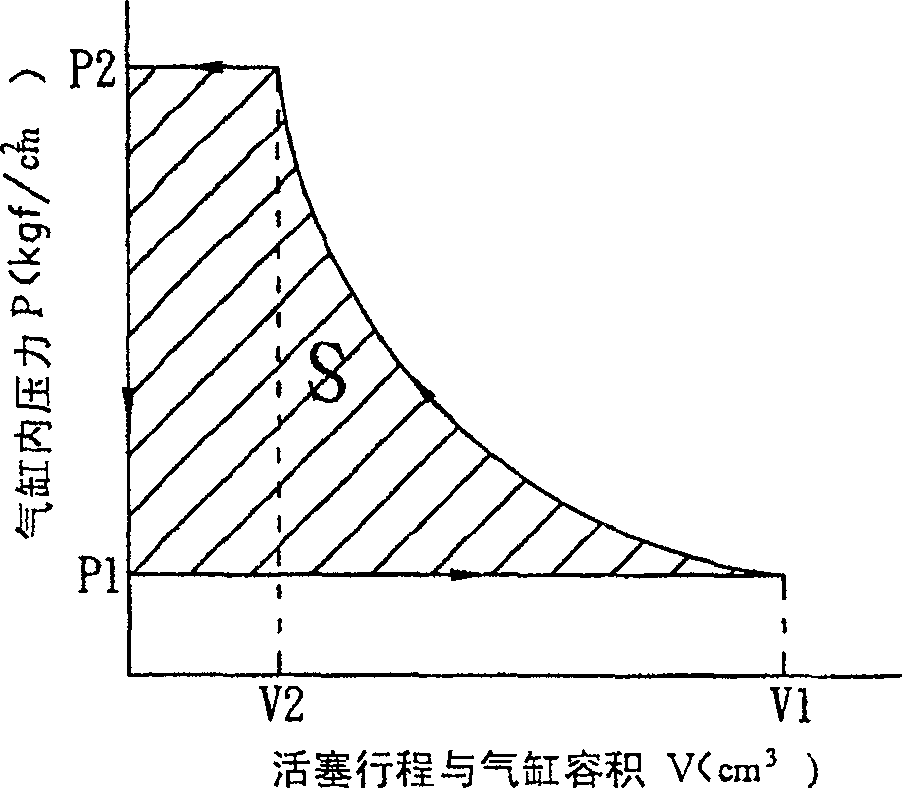
[0035] According to the intake structure of the reciprocating compressor disclosed in the present invention, firstly, according to the theoretical compression work of piston compression, please refer to figure 2 As shown, the compression work required for one compression of the piston is roughly the same no matter whether the temperature of the sucked refrigerant is higher or lower. In a reciprocating compressor, the low-temperature and low-pressure refrigerant gas entering the cylinder becomes high-temperature and high-pressure refrigerant gas after being compressed by the piston. The compression work required for one piston compression is the area of the cross-sectional area S in the figure. The state of the refrigerant gas during the piston compression movement:
[0036] ( P 2 P 1 ) = ( ...
PUM
 Abstract
Description
Claims
Application Information