A low-pressure flash pyrolysis flow tube reaction device based on a continuous molecular beam source

A technology of reaction device and flow tube, which is applied in the field of low-pressure flash pyrolysis flow tube reaction device, can solve the problems of high complete decomposition temperature, failure to reach pyrolysis reaction, easy annihilation, etc., achieve high initial decomposition temperature and reduce secondary The effect of short reaction and residence time

Active Publication Date: 2022-07-15
UNIV OF SCI & TECH OF CHINA
View PDF8 Cites 0 Cited by
  • Summary
  • Abstract
  • Description
  • Claims
  • Application Information

AI Technical Summary

Problems solved by technology

[0004] (1) The pyrolysis reaction cannot be carried out in a relatively high vacuum environment, and most active intermediate products such as free radicals are easily annihilated under normal pressure or high pressure and cannot be observed;
[0005] (2) Slow pyrolysis reaction device, the pyrolysis reaction is slow, secondary reactions are prone to occur, and the reaction intermediates cannot be accurately captured, that is, the reaction network cannot be accurately given;
[0006] (3) Discontinuous sampling, unable to conduct continuous sampling research by coupling molecular beam sampling system and photoionization mass spectrometry, which greatly increases the experimental period and error;
[0007] (4) The material of the reactor is mostly not up to the higher temperature range. There are many species that have a higher boiling point. The temperature requirement for complete decomposition of the species parent

Method used


Image

  • A low-pressure flash pyrolysis flow tube reaction device based on a continuous molecular beam source
  • A low-pressure flash pyrolysis flow tube reaction device based on a continuous molecular beam source
  • A low-pressure flash pyrolysis flow tube reaction device based on a continuous molecular beam source

Examples


Embodiment

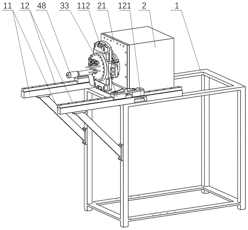
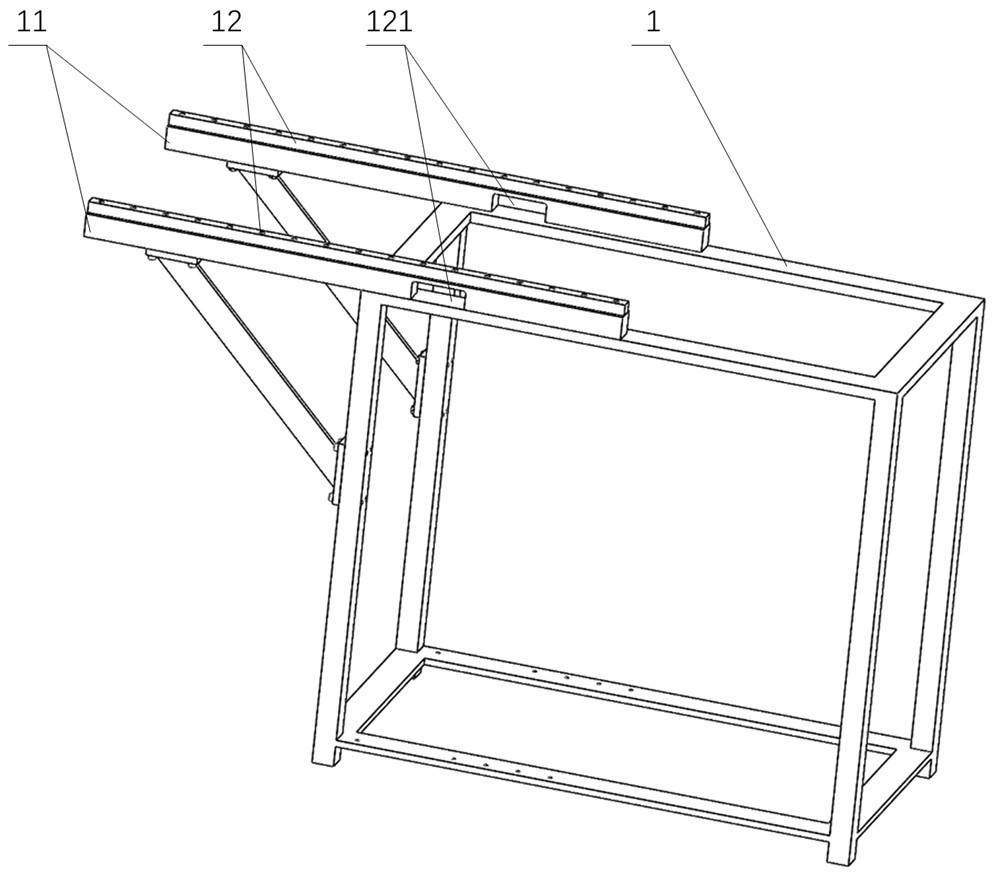
[0044] See figure 1 , figure 2 and image 3 , a low-pressure flash pyrolysis flow tube reaction device based on a continuous molecular beam source, comprising a cube-shaped test bench 1, a mounting mechanism, a flash pyrolysis mechanism and a vacuum box 2, the vacuum box 2 passing through the carriage 11 and a The sliding rails 12 are arranged on the upper end of the test bench 1; the test bench 1 is very convenient to move the instrument, and a pair of slide rails 12 can reduce a lot of disassembly and assembly work and reduce the wasted time for disassembly and assembly of the instrument.

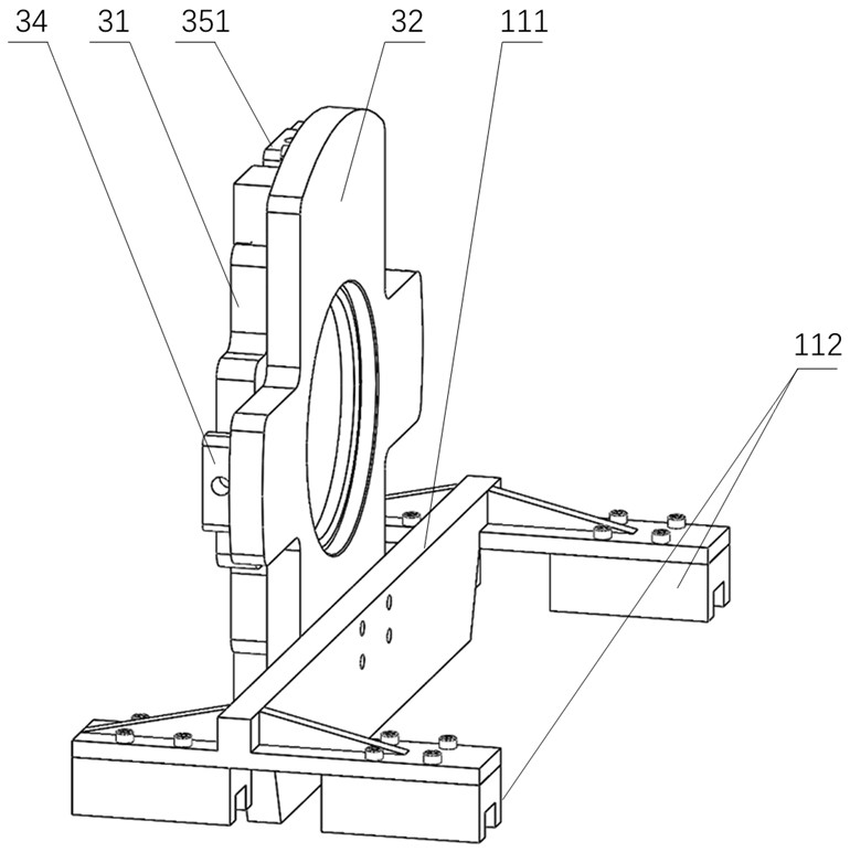
[0045] See Figure 4 and Figure 5 , the installation mechanism includes a first support plate 31, a second support plate 32 and an adjustment mechanism, and the first support plate 31 can be adjusted to be installed on one side of the second support plate 32 through the adjustment mechanism. The other side is fixedly installed on the front end surface of the vacuum box 2 through the...


PUM

PropertyMeasurementUnit
lengthaaaaaaaaaa

Abstract

The invention belongs to the technical field of pyrolysis instruments, in particular to a low-pressure flash pyrolysis flow tube reaction device based on a continuous molecular beam source. It includes a test bench, an installation mechanism, a flash pyrolysis mechanism and a vacuum box; the flash pyrolysis mechanism includes a cylindrical cavity horizontally arranged in the vacuum box, and a sample injection pipe, a water inlet pipe and a water outlet pipe arranged in the cylindrical cavity, and a water cooling chamber It is slidably arranged in the cavity at the other end of the cylindrical cavity, the other end of the injection tube penetrates the water cooling cavity, and the extension end is connected with a silicon carbide tube, and a pair of graphite electrodes is sleeved on the silicon carbide tube; the extension end of the push rod of the linear introducer A sliding table is arranged in the corresponding cylindrical cavity, the extension end of the push rod is fixedly connected with the sliding block, and the upper end of the sliding block is fixedly connected with the corresponding sampling tube. The silicon carbide tube of the invention is used as a reactor, and the graphite electrode is heated to realize rapid temperature rise and reduce secondary reactions, and can reduce the annihilation of active and important reaction intermediates such as free radicals under low pressure, and can realize continuous sampling and improve the reaction power of pyrolysis samples. study research.

Description

technical field [0001] The invention belongs to the technical field of pyrolysis reactors, and in particular relates to a low-pressure flash pyrolysis flow tube reaction device based on a continuous molecular beam source. Background technique [0002] In the current scientific research experiments, various reaction devices and equipment emerge in an endless stream, and a large number of experiments provide a broad data base for the development and verification of reaction kinetics. Pyrolysis reaction is the first stage of high temperature combustion, and it is a key process to explore the decomposition path of fuel and other samples in the initial stage. [0003] The current pyrolysis reactor mainly has the following problems: [0004] (1) The pyrolysis reaction cannot be carried out in a relatively high vacuum environment, and most active intermediate products such as free radicals are easily annihilated under normal pressure or high pressure, and cannot be observed; [0...

Claims


Application Information

Patent Timeline
Patent Type & Authority Patents(China)
IPC IPC(8): B01J3/00B01J3/02
CPCB01J3/006B01J3/02B01J3/002
Inventor 张锦阳官觊文王红王占东
Owner UNIV OF SCI & TECH OF CHINA
Why Eureka
Try Eureka