Compact pneumatic overall arrangement of compression system in aerial turbo fan engine

A technology of aerodynamic layout and compression system, which is applied in the direction of machines/engines, liquid fuel engines, mechanical equipment, etc., can solve the problems of increasing the axial length of the engine and aerodynamic loss, increasing the axial length of the compression system, and increasing the overall weight of the engine, etc. Achieve the effect of simplifying the structure complexity, reducing the number of parts, and enhancing the structural strength and stability

Inactive Publication Date: 2009-06-03
BEIHANG UNIV
View PDF2 Cites 0 Cited by
  • Summary
  • Abstract
  • Description
  • Claims
  • Application Information

AI Technical Summary

Problems solved by technology

The existence of the transition section increases the axial length of the compression system and increases the overall weight of the engine
In 2004, Europe launched the High-Load Transition Section Aerodynamic Research (AIDA) program, aiming to shorten the length of the transition section, but this plan is mainly aimed at turbofan engines with large bypass ratios, and it is difficult to completely remove the transition section
However, the compression of the turbofan engine of the existing design still uses a large height drop and a smooth transition section, which increases the axial length of the engine and the aerodynamic loss, which is extremely unfavorable for increasing the thrust-to-weight ratio of the turbofan engine.

Method used


Image

  • Compact pneumatic overall arrangement of compression system in aerial turbo fan engine
  • Compact pneumatic overall arrangement of compression system in aerial turbo fan engine
  • Compact pneumatic overall arrangement of compression system in aerial turbo fan engine

Examples


Embodiment Construction

[0025] In order to describe the present invention more clearly, this specific embodiment takes a compact design solution of a turbofan engine compression system as an example, and further illustrates the present invention with reference to the accompanying drawings.

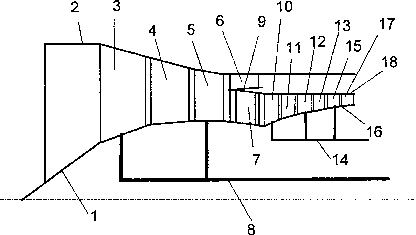
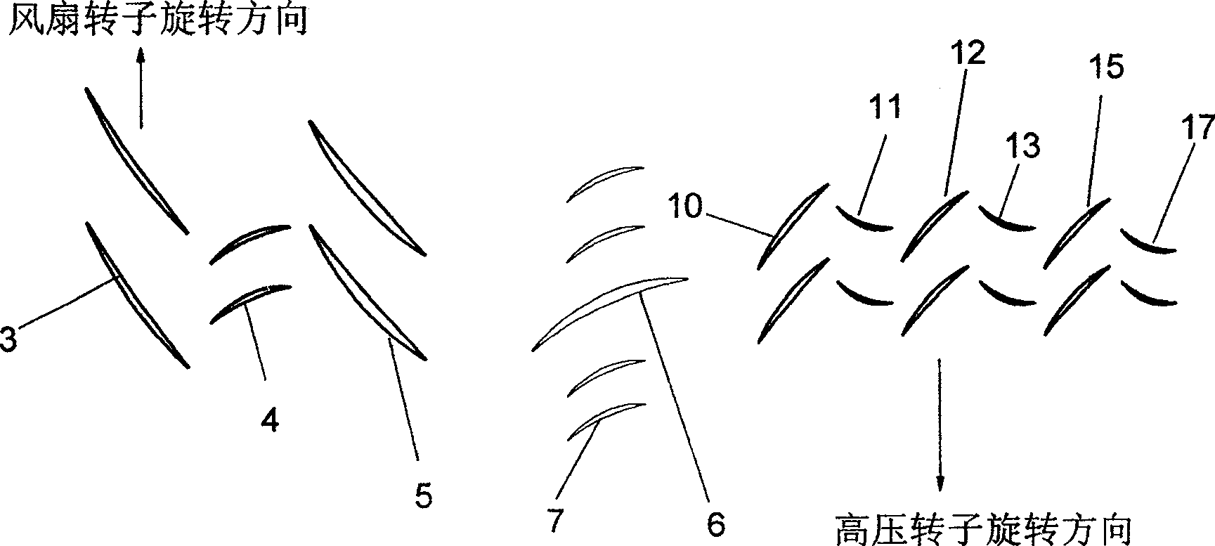
[0026] Table 1 shows the design parameters of the compression system. It can be seen from the table that the bypass ratio of this example is 0.262, which belongs to the compression system applied to engines with small bypass ratios. The blade tip tangential speed of the fan and the high-pressure compressor are both 500m / s. The fan cancels the outlet stator, and its first-stage rotor (3) adopts the design of equal pitch diameter, while the flow channel form of the first-stage stator (4) is between the equal pitch diameter and the equal inner diameter, and the second-stage rotor (5 ) is designed for equal inner diameter. In order to balance the design difficulty of each stage of the fan, the load factor of the fi...


PUM


Abstract

This invention relates to a design of compact pneumatic layout of the compression system of an aviation turbofan engine, which eliminates the transition section and fan output stator between the fan of an existing turbofan engine and a high pressure compressor and applies a diffusion cascade or a large corner expansion cascade to the inlet guide vane of the compressor to the outlet stator, the compressor inlet guide vane and bearing plate to a row of cascades and realizes compression of them, at the same time, it applies a high load design to the fan and the high pressure compressor to realize the same boost ratio with less stages.

Description

technical field [0001] The invention is a compact aerodynamic layout design method directly applied to the compression system of an aviation turbofan engine (referred to as turbofan engine), which can greatly reduce the number of parts and simplify the complex structure while realizing high pressure ratio, high efficiency and large margin Improve the compactness of the compression system, thereby increasing the thrust-to-weight ratio of the aero-engine. Background technique [0002] Turbofan engine is the mainstream of military aviation propulsion system at present, and thrust-to-weight ratio is an important index to measure its level. In recent decades, the thrust-to-weight ratio of turbofan engines has been greatly improved, and there is a tendency to further increase. The further improvement of the thrust-to-weight ratio will inevitably require reducing the weight of the engine as much as possible while further increasing the engine thrust. [0003] The structural size,...

Claims


Application Information

Patent Timeline
Patent Type & Authority Patents(China)
IPC IPC(8): F04D25/16F04D29/52F04D29/54
CPCF04D19/028
Inventor 周盛侯安平阙晓斌徐全勇
Owner BEIHANG UNIV
Why Eureka
Try Eureka