Exhaust gas system of a motor vehicle with a diesel engine

A diesel engine and exhaust system technology, applied to engine components, combustion engines, machines/engines, etc., can solve problems such as exhaust system simplification and particle filter unit cost reduction

Inactive Publication Date: 2009-06-10
ARVINMERITOR EMISSIONS TECH GMBH
View PDF11 Cites 0 Cited by
  • Summary
  • Abstract
  • Description
  • Claims
  • Application Information

AI Technical Summary

Problems solved by technology

But these ideas did not bring about a really significant reduction in the cost of the particulate filter unit, nor did they significantly simplify the operation of installing the exhaust system into the vehicle

Method used


Image

  • Exhaust gas system of a motor vehicle with a diesel engine
  • Exhaust gas system of a motor vehicle with a diesel engine

Examples


Embodiment Construction

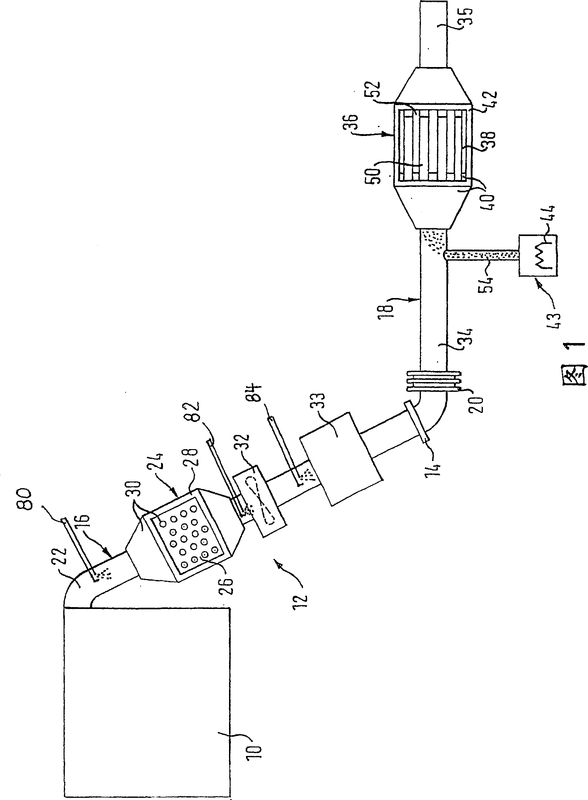
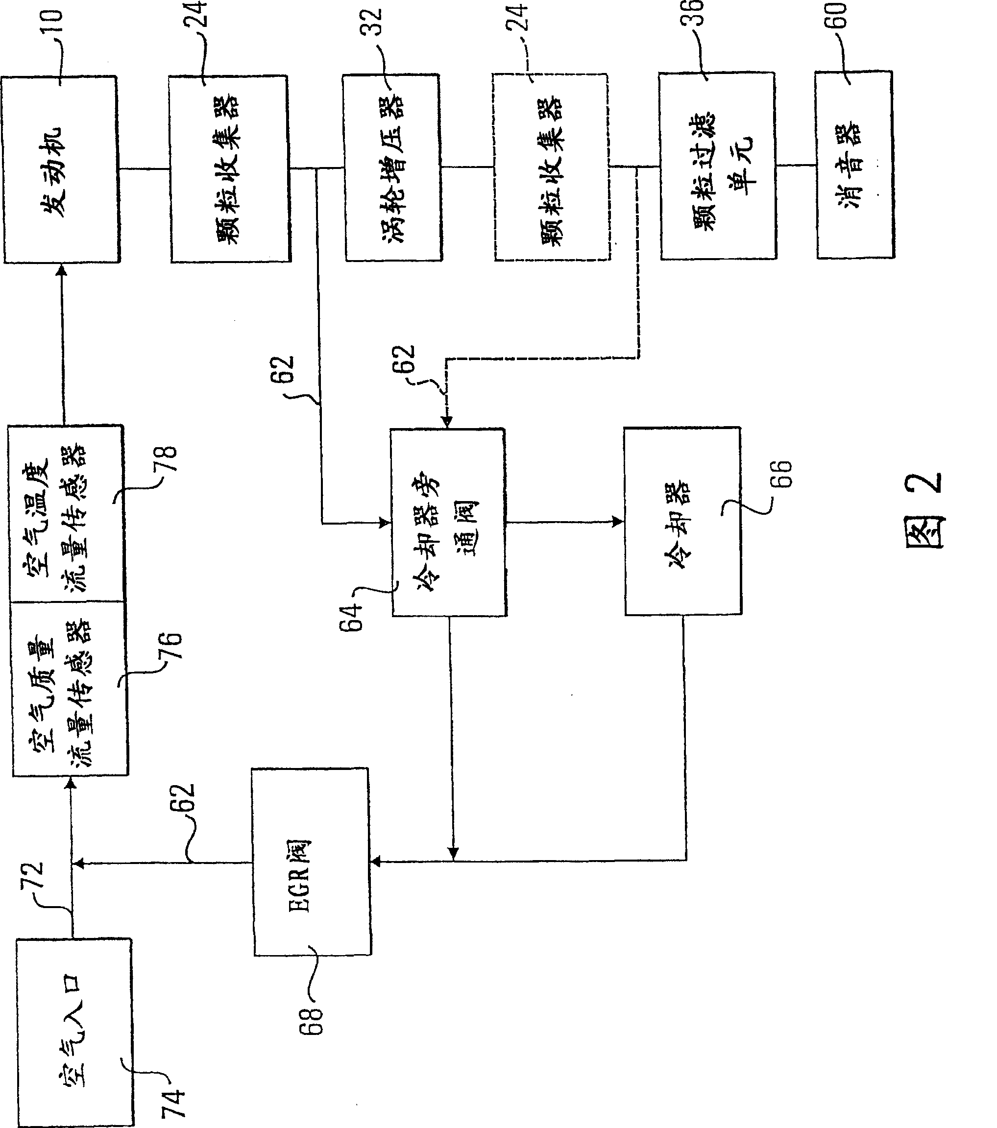
[0027]FIG. 1 shows a diesel engine 10 of a motor vehicle with a downstream exhaust system 12 . The exhaust system 12 has a manifold section 16 which extends as far as the flange 14 and a lower body section 18 adjoining the manifold section 16 downstream, which are connected to each other by vibration isolation means 20 .

[0028] The diesel engine 10 adjoins an exhaust pipe having a first pipe section 22 leading to a particle collector 24 which is arranged in the exhaust system 12 close to the engine.

[0029] The particle collector 24 includes an insert 26 made of ceramic foam or metal and disposed in an outer housing 28 of the particle collector 24 . An oxidation catalytic converter 30 is installed upstream of the insert 26 . However, the oxidation catalytic converter 30 is generally not required because the upstream portion of the insert 26 is properly coated. This means that the oxidation catalytic converter 30 is usually integrated in the insert 26 .

[0030] A turboch...


PUM


Abstract

An exhaust system for a motor vehicle with a diesel engine (10) comprising a particle filter unit (36) in which a particle collector (24) close to the engine is arranged ) and binds a part of the amount of particles contained in the exhaust gas flow, while another part of the amount of particles contained in the exhaust gas flow passes through the particle collector (24) to the particle filter unit (36). The particulate collector (24) is arranged close enough to the engine (10) that the particulate collector (24) is 2 The oxidation is at least partially regenerated.

Description

technical field [0001] The invention relates to an exhaust system of a motor vehicle with a diesel engine, which comprises a particle filter unit. Background technique [0002] The purpose of this type of particle filter, which may be referred to more simply as a soot filter, is to reduce the emission of exhaust gas particles. The core component of these particle filter units is a substrate, in particular a SiC substrate, which is accommodated in a separate outer casing, into which exhaust pipes are opened downstream and upstream of the particle filter unit. The particulate filter insert itself (ie the substrate) needs to be regenerated from time to time by the combustion of accumulated particulates on the filter surface. One of the most promising regeneration possibilities consists in introducing fuel directly into the exhaust gas immediately upstream of the particulate filter unit; among other reasons, the fuel should, if possible, be in vapor form so as not to overcool t...

Claims


Application Information

Patent Timeline
Patent Type & Authority Patents(China)
IPC IPC(8): F01N3/021F01N3/035F01N3/28F01N3/023F01N3/025F01N3/20F01N13/02F01N13/08F01N13/10F02B37/00
CPCF01N2610/06F01N13/02F01N3/0231Y02T10/144B01D2258/012F01N3/0842F01N3/035B01D53/9418F01N3/0814F01N3/2066B01D53/944F01N2610/02F01N2610/03B01D2257/404F01N2013/023F01N13/1816F01N3/0253F01N3/103B01D2251/2067F01N2250/02B01D53/9459Y02T10/24B01D53/9477F01N2340/06F02B37/00B01D53/8653F01N13/0093F01N13/009Y02A50/20Y02T10/12F01N3/021F01N3/023F01N3/02
Inventor 马尔科·拉纳利
Owner ARVINMERITOR EMISSIONS TECH GMBH
Why Eureka
Try Eureka