Filament spot circuit of vacuum fluorescent display screen

A display screen and vacuum technology, applied in the direction of static indicators, instruments, etc., can solve the problems of unstable output voltage, large volume, high cost, etc., and achieve the effects of stable voltage, reduced volume, and reduced production difficulty

Inactive Publication Date: 2009-06-10
ZHEJIANG DAHUA TECH CO LTD
View PDF4 Cites 0 Cited by
  • Summary
  • Abstract
  • Description
  • Claims
  • Application Information

AI Technical Summary

Problems solved by technology

[0003] The object of the present invention is to provide a vacuum fluorescent display filament lighting circuit for the disadvantages of high cost, large volume and unstable output voltage in the prior art

Method used


Image

  • Filament spot circuit of vacuum fluorescent display screen
  • Filament spot circuit of vacuum fluorescent display screen
  • Filament spot circuit of vacuum fluorescent display screen

Examples


Embodiment 1

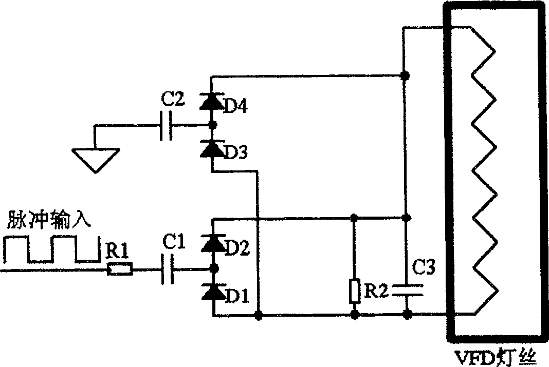
[0015] The present invention can adopt the DC drive mode, take a cycle of pulse width energy on the system power supply (such as 3.3V, 2.5V, 1.8V, 1.2V, etc.) characteristics), a DC blocking capacitor is added to the positive pulse and the power supply ground to achieve the purpose of electrical insulation from the logic working ground, and a resistor is connected in series before the DC blocking capacitor to adjust the pulse energy and adjust the brightness of the vacuum fluorescent display. The capacitance of the DC blocking capacitor determines the size of its coupling energy. Add a bridge rectifier at the back end of the DC blocking capacitor, and then add a capacitor filter to convert the pulse into DC, and add a large resistance resistor to drain Let off the excess charge and complete the filament DC drive mode of the vacuum fluorescent display.

[0016] Specifically, such as figure 1 As shown, the vacuum fluorescent display filament lighting circuit is a DC drive mode ...

Embodiment 2

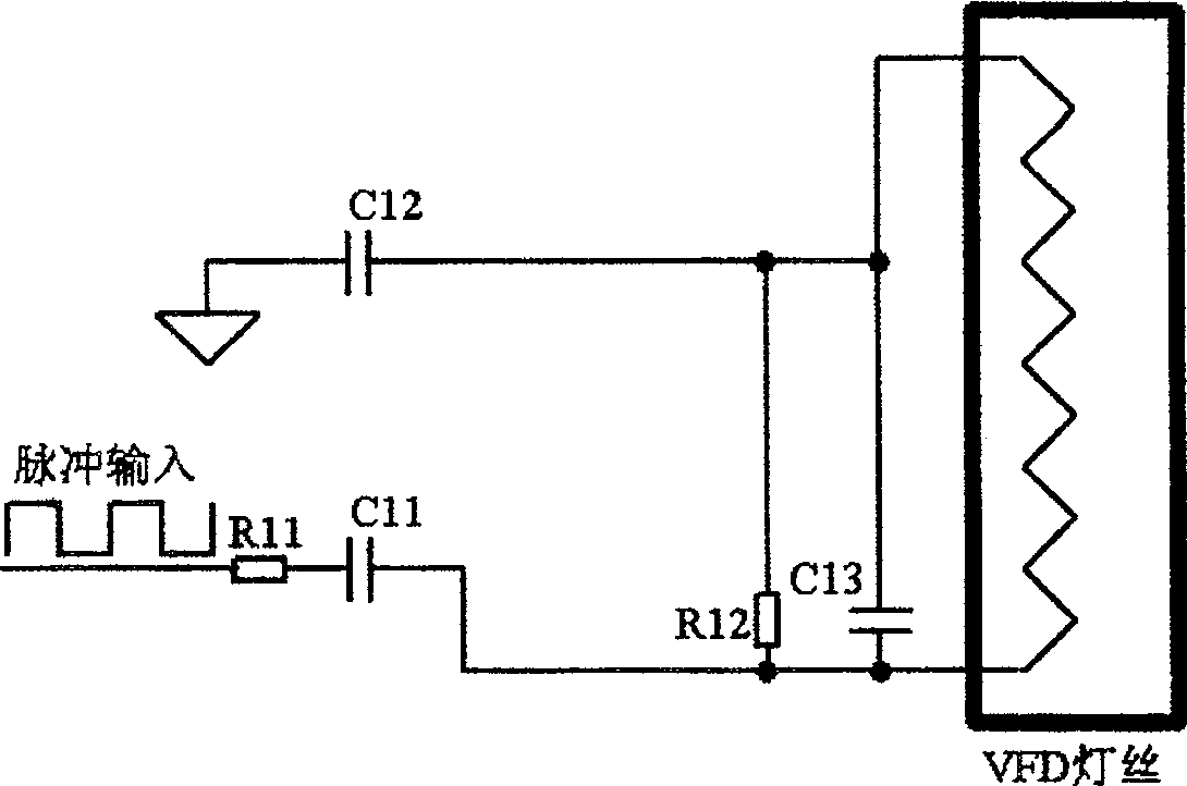
[0021] The present invention can also adopt AC drive mode. The principle of AC drive mode is as follows: a resistor is connected in series before the DC blocking capacitor to adjust the pulse energy, no bridge rectifier bridge is added at the rear end of the DC blocking capacitor, and it is directly connected to the two poles of the filament of the vacuum fluorescent display (VFD), and then And add a large resistance resistor to discharge excess charge for AC power supply mode.

[0022] Specifically, such as image 3 As shown, the vacuum fluorescent display filament lighting circuit of the present invention is an AC drive mode circuit, which is mainly composed of resistors R11-R12 and capacitors C11-C13; one end of the resistor R11 is connected to the pulse input signal line, and the other end is connected to the capacitor C11 The other end of the capacitor C11 is connected to the resistor R12 and the capacitor C13 respectively, the other end of the resistor R12 is connected ...


PUM


Abstract

A lightening circuit of lamp filament on vacuum fluorescent display screen is prepared as utilizing the starting-stopping character of capacity to couple energy onto lamp filament of vacuum fluorescent display screen through capacity electric field mode to make current flow through lamp filament of vacuum fluorescent display screen for realizing purpose of heating lamp filament.

Description

technical field [0001] The invention relates to the field of vacuum displays, in particular to a vacuum fluorescent display (VFD) filament lighting circuit. Background technique [0002] At present, the known vacuum fluorescent display filament lighting circuit needs to work floating. In practical applications, such as automobiles, outdoor portable instruments, home appliances, industrial control, etc., DC-AC conversion circuits are generally used to obtain pulse voltages for vacuum fluorescent displays. The filament provides power. The use of a DC-AC conversion circuit requires a transformer, which transmits energy through a magnetic field. Using a transformer to complete the isolation and floating design of the power supply requires two windings, namely a primary winding and a secondary winding. The winding needs to change the current to induce an alternating magnetic field on the magnetic material, and then there is an induced electromotive force on the secondary winding...

Claims


Application Information

Patent Timeline
Patent Type & Authority Patents(China)
IPC IPC(8): G09G3/06G09G3/22
Inventor 漆永林傅利泉朱江明王增锹吴军应必善
Owner ZHEJIANG DAHUA TECH CO LTD
Why Eureka
Try Eureka