
Gas-driven guided missile swing nozzle

A technology for nozzles and missiles, which is applied in the direction of machines/engines, jet propulsion devices, rocket engine devices, etc. It can solve the problems of complex mechanical structure of servo motors, difficulties in mass production, and high power requirements, and achieve simple and effective control methods. The effect of reducing production difficulty and reducing processing steps

Active Publication Date: 2021-12-07
NANJING UNIV OF SCI & TECH
View PDF6 Cites 0 Cited by
  • Summary
  • Abstract
  • Description
  • Claims
  • Application Information

AI Technical Summary

Problems solved by technology

[0003] A commonly used technical method is to use the servo motor as the source of the driving force for the nozzle swing. However, the servo motor has a complex mechanical structure and high cost, and it will be difficult to integrate into the overall design of the missile. In order to generate a large control torque, it is necessary to The power is high, so the requirements for the power supply are also extremely high, which brings certain difficulties to mass production

Method used


Image

  • Gas-driven guided missile swing nozzle
  • Gas-driven guided missile swing nozzle
  • Gas-driven guided missile swing nozzle

Examples


Embodiment Construction

[0038] In order to make the purpose, technical solution and advantages of the present application clearer, the implementation manners of the present application will be further described in detail below in conjunction with the accompanying drawings.

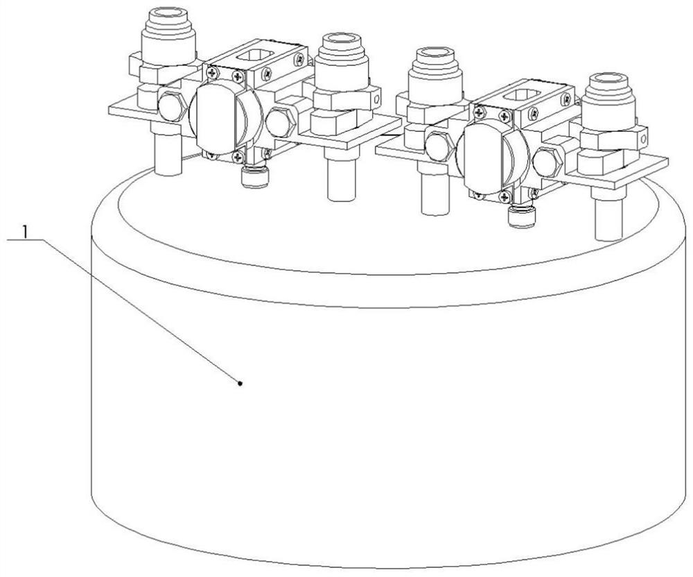
[0039] Please refer to figure 1 , which exemplarily shows a structural schematic diagram of a gas-driven missile swing nozzle provided by an embodiment of the present application.

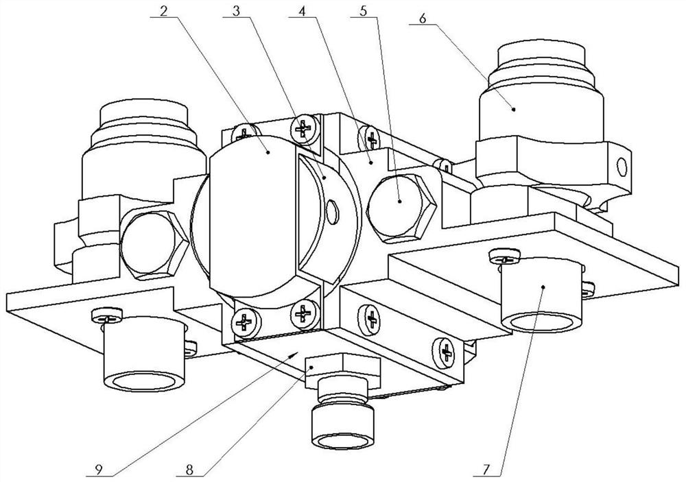
[0040] The gas-driven missile oscillating nozzle provided in the embodiment of the present application includes a combustion chamber 1 and two single-axis oscillating dual nozzle assemblies arranged side by side and symmetrically on the same end face of the combustion chamber 1 . The single-axis swing double nozzle assembly is connected to the combustion chamber 1 through the pipe group.

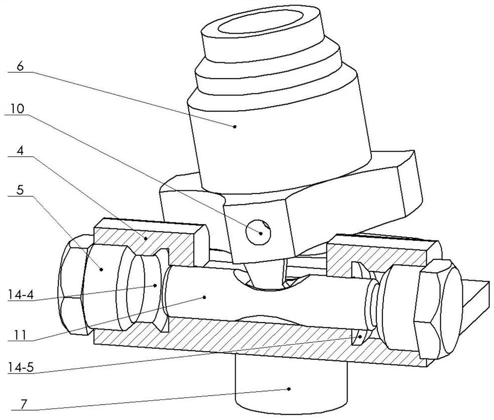
[0041] The components of the two single-axis swing double nozzle assemblies are the same, and the structures are symmetrical. The single-axis swing double nozzle ...


PUM


Abstract

The invention provides a gas-driven guided missile swing nozzle. The guided missile swing nozzle comprises a combustion chamber and two single-shaft swing double-nozzle assemblies which are symmetrically arranged on the same end face of the combustion chamber in parallel; and the single-shaft swing double-nozzle assemblies are connected into the combustion chamber through pipeline sets, the two single-shaft swing double-nozzle assemblies are the same in component and symmetrical in structure, and the single-shaft swing double-nozzle assemblies are integrally assembled through splicing. According to the gas-driven guided missile swing nozzle, the requirement for a power source is low, and operation of the whole swing nozzle can be controlled only by connecting a standard missile-borne power source to enable an electromagnet to work; and the gas-driven guided missile swing nozzle adopts the split-type symmetrical design, an internal gas path channel is split into different short sections, and the split parts are simple in structure, so that the machining and production difficulty is greatly reduced, the manufacturing cost is reduced, and a control method is simple and effective.

Description

technical field [0001] The application relates to the technical field of missile thrust vector control equipment, in particular to a gas-driven missile swing nozzle. Background technique [0002] Traditional rocket engine nozzles can only provide thrust in the direction of the projectile axis, and the missile usually needs to rely on the asymmetric aerodynamic moment generated by the deflection of the aerodynamic rudder to achieve attitude adjustment. With the gradual improvement of the missile's requirements for maneuverability and the increasing angle of attack, it is difficult for the aerodynamic rudder to meet the operational requirements. In contrast, thrust vectoring technology generates the torque required to control the missile by controlling the offset of the main thrust relative to the bomb axis, no longer relying on aerodynamic force, and can still generate a large control torque even at low speeds or high altitudes. The thrust vector control system using the swi...

Claims


Application Information

Patent Timeline
Patent Type & Authority Applications(China)
IPC IPC(8): F02K9/97F02K9/80
CPCF02K9/97F02K9/805
Inventor 罗飞封锋向熙
Owner NANJING UNIV OF SCI & TECH
Learn More