
Light-emitting device

A technology of light-emitting device and light-emitting unit, which is applied in the direction of electrical components, electrical solid-state devices, circuits, etc.

Inactive Publication Date: 2009-06-10
GIO OPTOELECTRONICS CORP
View PDF4 Cites 0 Cited by
  • Summary
  • Abstract
  • Description
  • Claims
  • Application Information

AI Technical Summary

Problems solved by technology

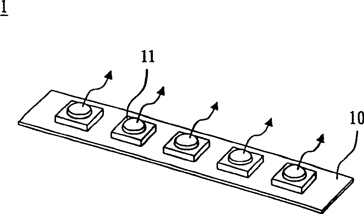
Therefore, how to provide a light-emitting device that can avoid the open circuit phenomenon caused by the damage of a single light-emitting element is one of the current important issues.

Method used


Image

  • Light-emitting device
  • Light-emitting device
  • Light-emitting device

Examples


Embodiment Construction

[0042] In order to further explain the technical means and effects adopted by the present invention to achieve the intended purpose of the invention, the specific implementation, structure, features and effects of the light-emitting device proposed according to the present invention will be described in detail below in conjunction with the accompanying drawings and preferred embodiments. The description is as follows.

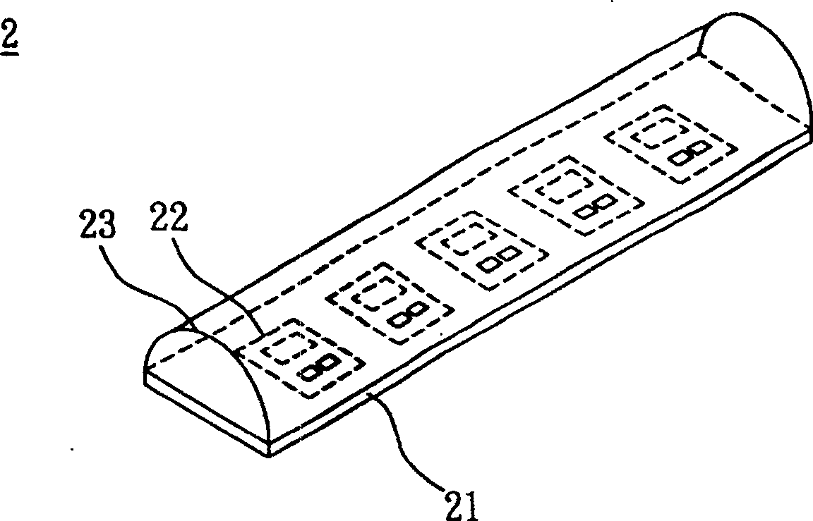
[0043] see Figure 2A , Figure 2B as shown, Figure 2A is a schematic diagram of the composition of the light emitting device in a preferred embodiment of the present invention, Figure 2B It is another schematic diagram of the structure of the light emitting device in the preferred embodiment of the present invention. The light-emitting device 2 according to a preferred embodiment of the present invention includes a circuit substrate 21, a plurality of light-emitting units 22, and a light-transmitting encapsulation layer 23, wherein:

[0044] The circuit su...


PUM


Abstract

The disclosed luminous device comprises: a circuit base, some luminous units serial arranged on the base, and a transparent package layer covering the luminous units, wherein the LED in every luminous unit connects as open circuit in parallel. Thereby, this invention improves product reliability, and can reduce cost greatly.

Description

technical field [0001] The invention relates to a light-emitting device, in particular to a light-emitting device with a light-emitting diode which can avoid the open circuit phenomenon caused by the damage of the light-emitting element and can also reduce the manufacturing cost. Background technique [0002] The application range of light-emitting diodes is quite extensive. In addition to being used as general lighting, light-emitting diodes are more recently used as light sources for backlight modules of display devices. As far as the backlight modules of displays are concerned, they can generally be divided into two categories: direct-type backlight modules and edge-type backlight modules. A plurality of light-emitting devices (light-emitting modules) are used in the direct-type backlight module, while one light-emitting device is mostly used in the side-light type backlight module. What needs to be specially explained here is that as the size of the display is different...

Claims


Application Information

Patent Timeline
Patent Type & Authority Patents(China)
IPC IPC(8): H01L25/00H01L25/16
Inventor 陈宏男
Owner GIO OPTOELECTRONICS CORP
Learn More