Voltage adjustable drive in AC power source of sine wave

An AC power supply, sine wave technology, applied in the direction of AC power input conversion to AC power output, AC power input conversion to DC power output, electrical components, etc. problem, to achieve the effect of good dynamic stability, simple circuit structure, and improved application efficiency

Inactive Publication Date: 2009-06-10
RGB LIGHTING EQUIP
View PDF6 Cites 0 Cited by
  • Summary
  • Abstract
  • Description
  • Claims
  • Application Information

AI Technical Summary

Problems solved by technology

[0004] The purpose of the present invention is to design a sine wave AC circuit based on integrated circuit chip control technology for the problems of waveform distortion in the existing thyristor voltage regulating circuit and the problems of large power consumption and complicated circuit in the power switch tube voltage regulating circuit. power regulator driver

Method used


Image

  • Voltage adjustable drive in AC power source of sine wave
  • Voltage adjustable drive in AC power source of sine wave
  • Voltage adjustable drive in AC power source of sine wave

Examples


Embodiment 1

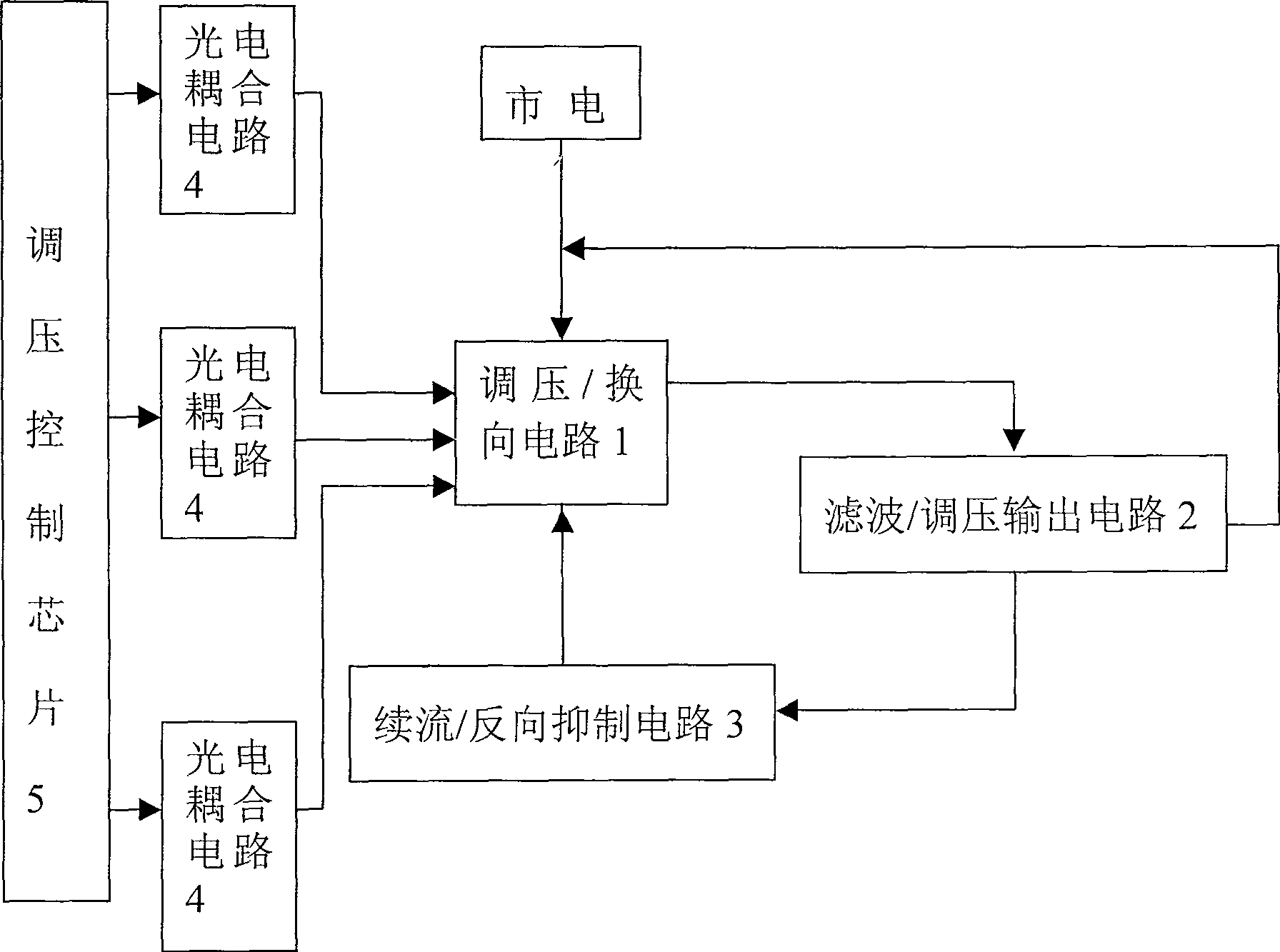
[0024] Such as figure 1 As shown, the sine wave AC power voltage regulation driver of the present invention includes a voltage regulation / commutation circuit 1, a filter / voltage regulation output circuit 2, a freewheeling / reverse suppression circuit 3, a photoelectric coupling circuit 4, and a voltage regulation control chip 5. The voltage regulation control chip 5 is connected to the control terminal of the voltage regulation / commutation circuit 1 through the photoelectric coupling circuit 4, the output of the voltage regulation / commutation circuit 1 is connected to the input terminal of the filter / voltage regulation output circuit 2, and the filter / voltage regulation output circuit One of the outputs of 2 is connected to the power supply input terminal of the voltage regulation / reversing circuit 1, the other is connected to the input terminal of the freewheeling / reverse suppression circuit 3, and the output of the freewheeling / reverse suppression circuit 3 is connected to the...

Embodiment 2

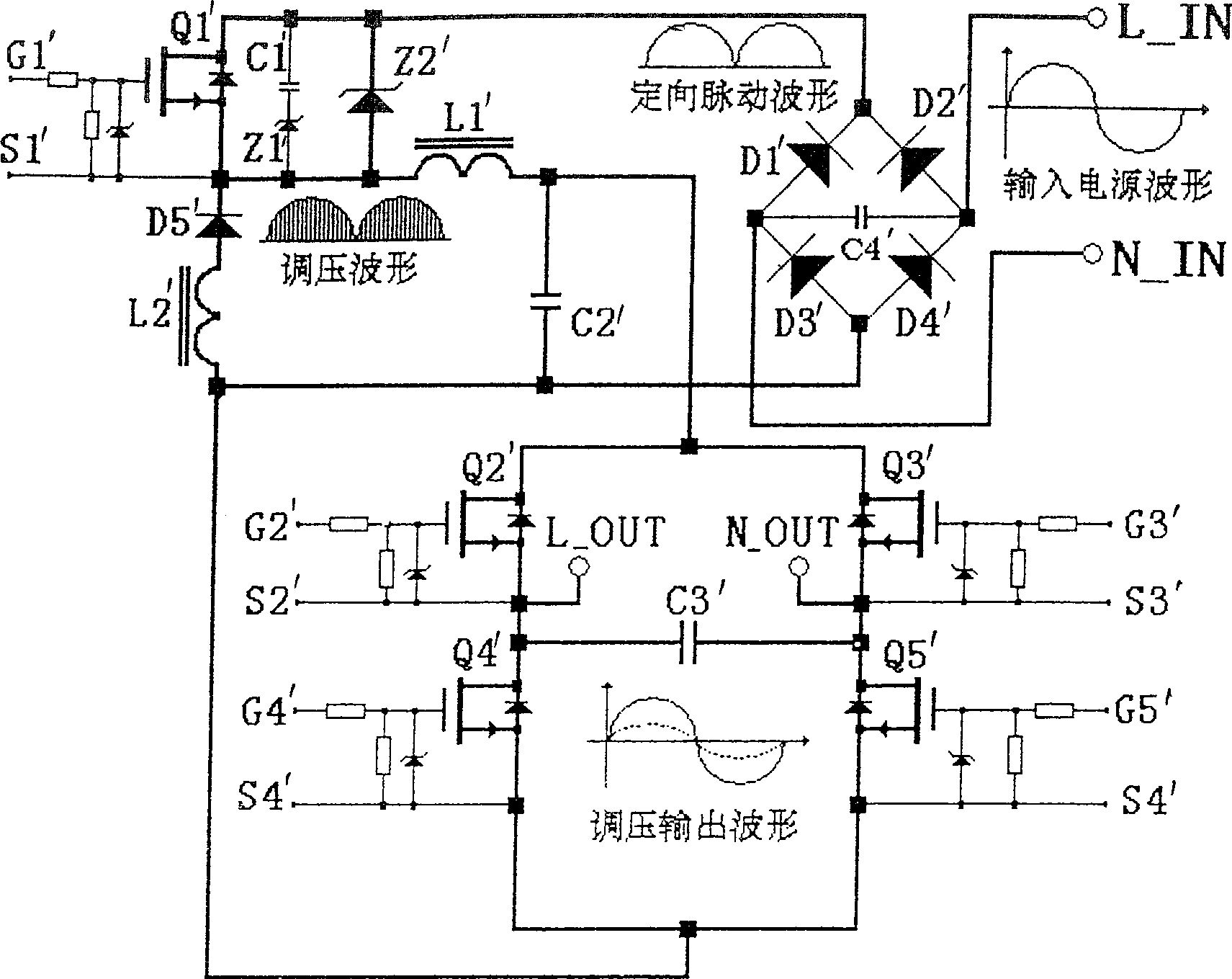
[0036] Such as image 3 As shown, it gives the figure 1 Another specific embodiment of the electrical principle block diagram shown in .

[0037] Among them: the voltage regulation / commutation circuit 1 in the electrical principle block diagram is composed of switch tubes Q1'-Q5' and inductor L1', and its freewheeling input terminal is drawn from the source of the switch tube Q1' to connect to the freewheeling / reverse suppression circuit 3's output terminal, its power supply input terminal is drawn from the drain of Q1', and connected to the two ends L-IN and N-IN of the mains power supply through the bridge rectifier block D1'-D4', and its control terminal is connected from the switch tube Q1 The grid of '-Q5' is drawn out, and connected to the voltage regulation control chip 5 through respective resistance networks and photoelectric coupling circuits 4 (this chip can be made by writing specific software into existing integrated circuits, and the realization of this chip fun...


PUM


Abstract

The voltage regulating drive includes voltage regulating / switching circuit, filtering / voltage regulating output circuit, afterflow / backward inhibition circuit, opto-electronic (OE) coupling circuit, voltage regulating control chip. Characters are that through OE coupling circuit, the chip is connected to the control end of the voltage regulating / switching circuit. The output of the voltage regulating / switching circuit is connected to the input end of the filtering / voltage regulating output circuit. One output route of the filtering / voltage regulating output circuit is connected to the input end of electrical source of the voltage regulating / switching circuit, and the other output route is connected to the input end of the inhibition circuit. Output of the inhibition circuit is connected to the afterflow input end of the voltage regulating / switching circuit. Comparing prior art, the invention possesses advantages no waveform distortion, small volume, and energy saving.

Description

technical field [0001] The invention relates to an AC power voltage regulating driver, in particular to an energy-saving AC voltage regulating driver without output waveform distortion, in particular to a sine wave AC power voltage regulating driver. Background technique [0002] The current sine wave AC power voltage regulating device is mainly composed of thyristors, and the thyristors generally have the problems of voltage regulation output waveform distortion and serious harmonic interference in the process of AC voltage regulation. The reason is: thyristors The control electrode of the control pole can only be triggered to turn on, but not to be turned off. After the thyristor is turned on, it can only be turned off when the current of the thyristor is less than the minimum value for maintaining the conduction (automatically shut off when zero crossing in the AC power supply). Due to the working characteristics of the thyristor, it is difficult to technically process th...

Claims


Application Information

Patent Timeline
Patent Type & Authority Patents(China)
IPC IPC(8): H02M5/22H02M5/293
CPCH02M7/538
Inventor 韩腊生
Owner RGB LIGHTING EQUIP
Why Eureka
Try Eureka