Stator, motor, and method of manufacturing such stator

A stator and rotor technology, which is used in the manufacture of stator/rotor bodies, motor generators, and prefabricated windings embedded in motors. issues such as

Inactive Publication Date: 2009-07-01
HONDA MOTOR CO LTD
View PDF16 Cites 0 Cited by
  • Summary
  • Abstract
  • Description
  • Claims
  • Application Information

AI Technical Summary

Problems solved by technology

In addition, due to this inductance loss, the control content of the salient pole motor becomes complicated.
[0007] In the three-phase motor of the above-mentioned prior art, since windings for each of the three phases are required, it is difficult to suppress the increase in the number of parts required for the structure of the stator, and there is a problem of winding the windings for each phase. Problems requiring complicated processes for operation
[0008] Moreover, in the stator in which the winding is wound by the wave winding method, it is difficult to increase the winding space factor between adjacent teeth, and the height of the winding end is reduced to reduce the axial dimension of the motor, making it difficult to improve Problems of mountability on vehicles etc.

Method used


Image

  • Stator, motor, and method of manufacturing such stator
  • Stator, motor, and method of manufacturing such stator
  • Stator, motor, and method of manufacturing such stator

Examples


no. 1 approach

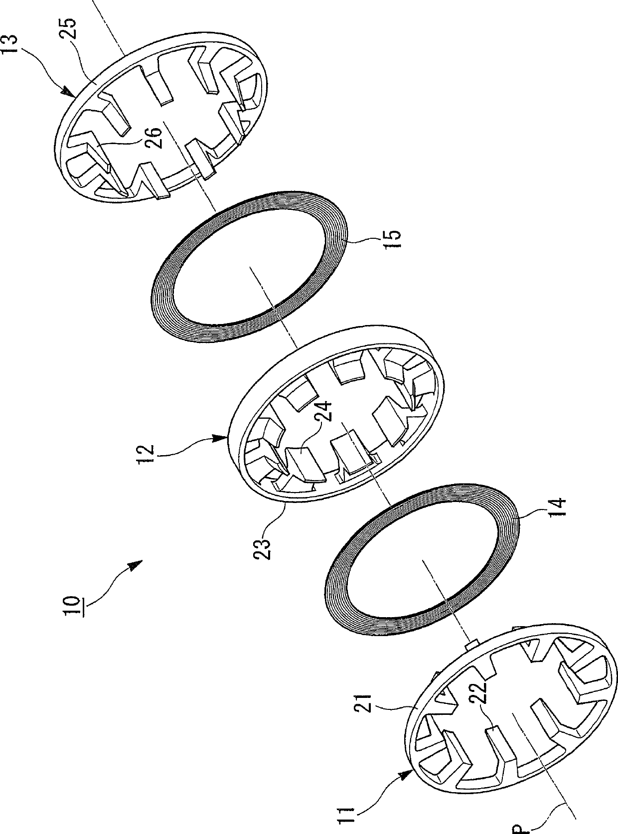
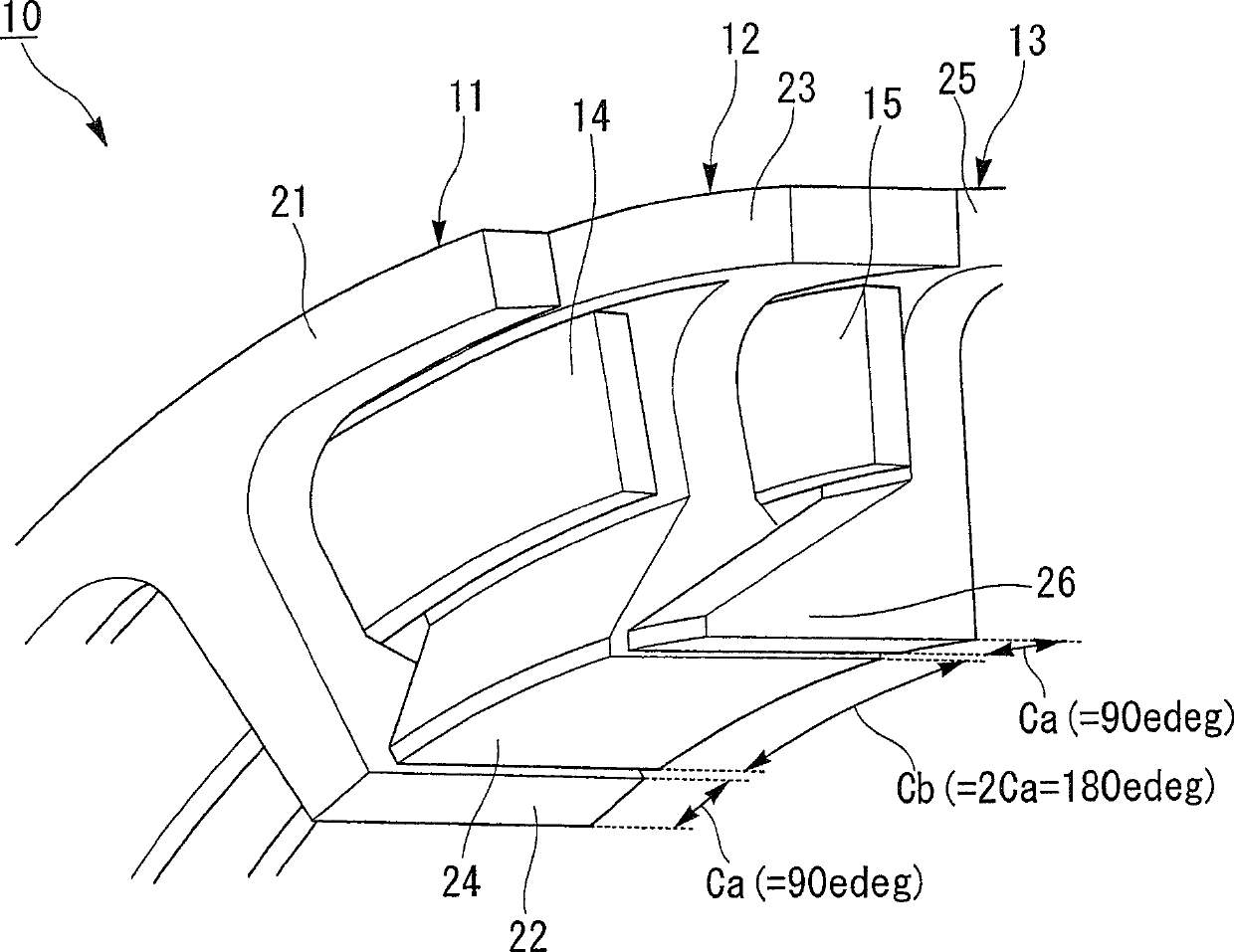
[0198] Hereinafter, a first embodiment of the stator of the present invention will be described with reference to the drawings.

[0199] The stator 10 of this embodiment constitutes, for example, a salient-pole motor mounted on a hybrid vehicle as a drive source of the vehicle together with an internal combustion engine, and is configured, for example, in a structure in which the internal combustion engine, the salient-pole motor, and a transmission are directly connected in series. In a parallel hybrid vehicle, at least the driving force of either the internal combustion engine or the salient-pole motor is transmitted to the drive wheels of the vehicle through a transmission.

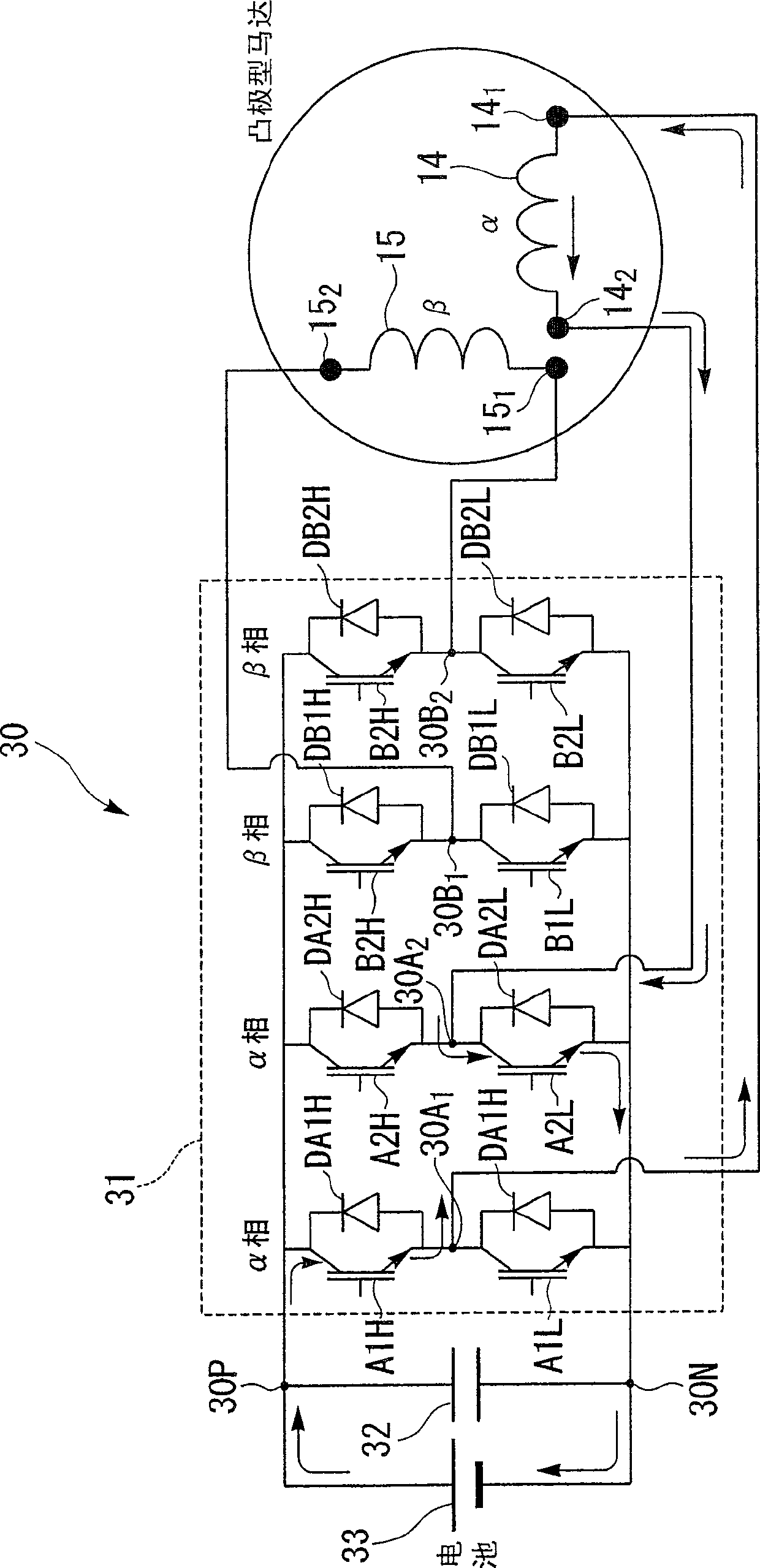
[0200] Also, when the driving force is transmitted from the driving wheel side to the salient pole motor when the vehicle decelerates, the salient pole motor functions as a generator to generate so-called regenerative braking force, and recovers the kinetic energy of the vehicle body as electric energy ...

no. 2 approach

[0232] Hereinafter, a second embodiment of the stator of the present invention will be described with reference to the drawings.

[0233] As in Embodiment 1, the stator 110 of this embodiment constitutes, for example, a salient-pole motor mounted on a hybrid vehicle as a driving source of the vehicle together with an internal combustion engine. For example, the internal combustion engine, the salient-pole motor, and the transmission In a parallel hybrid vehicle having a structure in which the devices are directly coupled, at least the driving force of either the internal combustion engine or the salient pole motor is transmitted to the driving wheels of the vehicle through the transmission.

[0234] When the driving force is transmitted from the drive wheel side to the salient pole motor when the vehicle decelerates, the salient pole motor functions as a generator to generate so-called regenerative braking force, and recovers the kinetic energy of the vehicle body as electric e...

no. 3 approach

[0310] Hereinafter, a third embodiment of the stator of the present invention will be described with reference to the drawings.

[0311] The stator 50 of the third embodiment differs from the stator 110 of the above-mentioned second embodiment in that the U-phase loop winding 54 and the W-phase loop winding 55 do not have the respective U-phase meandering parts 131 and W-phase meandering parts 131 . Section 132 of this.

[0312] Hereinafter, the description of the same parts as those of the second embodiment will be simplified or omitted.

[0313] For example Figure 24 and Figure 25 As shown, the stator 50 of this embodiment includes: a U-phase stator ring 51, a V-phase stator ring 52, a W-phase stator ring 53, and a U-phase stator ring 53 for each of the three phases composed of a U-phase, a V-phase, and a W-phase. Two-phase U-phase toroidal winding 54 and W-phase toroidal winding 55 constituted by a phase and a W-phase.

[0314] The U-phase stator ring 51 has a substan...


PUM


Abstract

Stator rings (11), (12), and (13) are sequentially stacked and connected along the axial direction so as to be arranged coaxially with the axis (P). The claw-shaped induction poles (22), (24), and (26) are arranged in sequence along the circumferential direction. When the axial end surface of the A-phase back yoke (21) is in contact with the other axial end surface of the B-phase back yoke (23), each claw-shaped induction pole (22) arranged at a predetermined interval in the axial direction, The base end portions of (24) sandwich and fix the α-phase toroidal winding (14) from both sides in the axial direction. When one axial end surface of the B-phase back yoke (23) is in contact with the axial end surface of the D-phase back yoke (25), each claw-shaped induction pole (242), The base ends of 26) clamp and fix the β-phase toroidal coil (15) from both sides in the axial direction.

Description

technical field [0001] The invention relates to a stator, a motor and a method for manufacturing the stator. [0002] This application is for: Japanese Patent Application No. 2005-055670 filed on March 1, 2005, Japanese Patent Application No. 2005-055671, Japanese Patent Application No. 2005-055672, Japan filed on March 2, 2005 Priority of Patent Application No. 2005-057141, Japanese Patent Application No. 2005-057142, Japanese Patent Application No. 2005-306778 filed on October 21, 2005, and Japanese Patent Application No. 2005-306780, incorporated herein by reference its content. Background technique [0003] Conventionally, as a conventional salient pole motor, it is known that, for example, three-phase stator rings composed of U phase, V phase, and W phase are arranged so as to be superimposed coaxially along the axial direction. On the ring-shaped winding installation part formed between adjacent stator rings, the ring-shaped windings that generate the rotating magnet...

Claims


Application Information

Patent Timeline
Patent Type & Authority Patents(China)
IPC IPC(8): H02K3/18H02K1/14H02K15/02H02K15/04H02K15/06
Inventor 高桥忠伸今井信幸青木新泷泽大二郎
Owner HONDA MOTOR CO LTD
Why Eureka
Try Eureka