
Probe of magnetocardiograph

A magnetocardiograph and axis technology, applied in medical science, sensors, diagnostic recording/measurement, etc., can solve problems such as measurement errors, achieve high measurement accuracy, easy operation, and reduce measurement errors

Active Publication Date: 2009-07-08
BEIJING SQUID QUANTUM TECH
View PDF5 Cites 0 Cited by
  • Summary
  • Abstract
  • Description
  • Claims
  • Application Information

AI Technical Summary

Problems solved by technology

[0003] The technical problem to be solved by the present invention is to provide a signal receiving device based on a high-temperature superconducting quantum interferometer for biological magnetic detection equipment, which can solve the problem that a magnetocardiograph needs to move the probe multiple times horizontally and vertically to complete a measurement of the basic points of the magnetic field. device, which is prone to the problem of measurement error

Method used


Image

  • Probe of magnetocardiograph
  • Probe of magnetocardiograph
  • Probe of magnetocardiograph

Examples


Embodiment 1

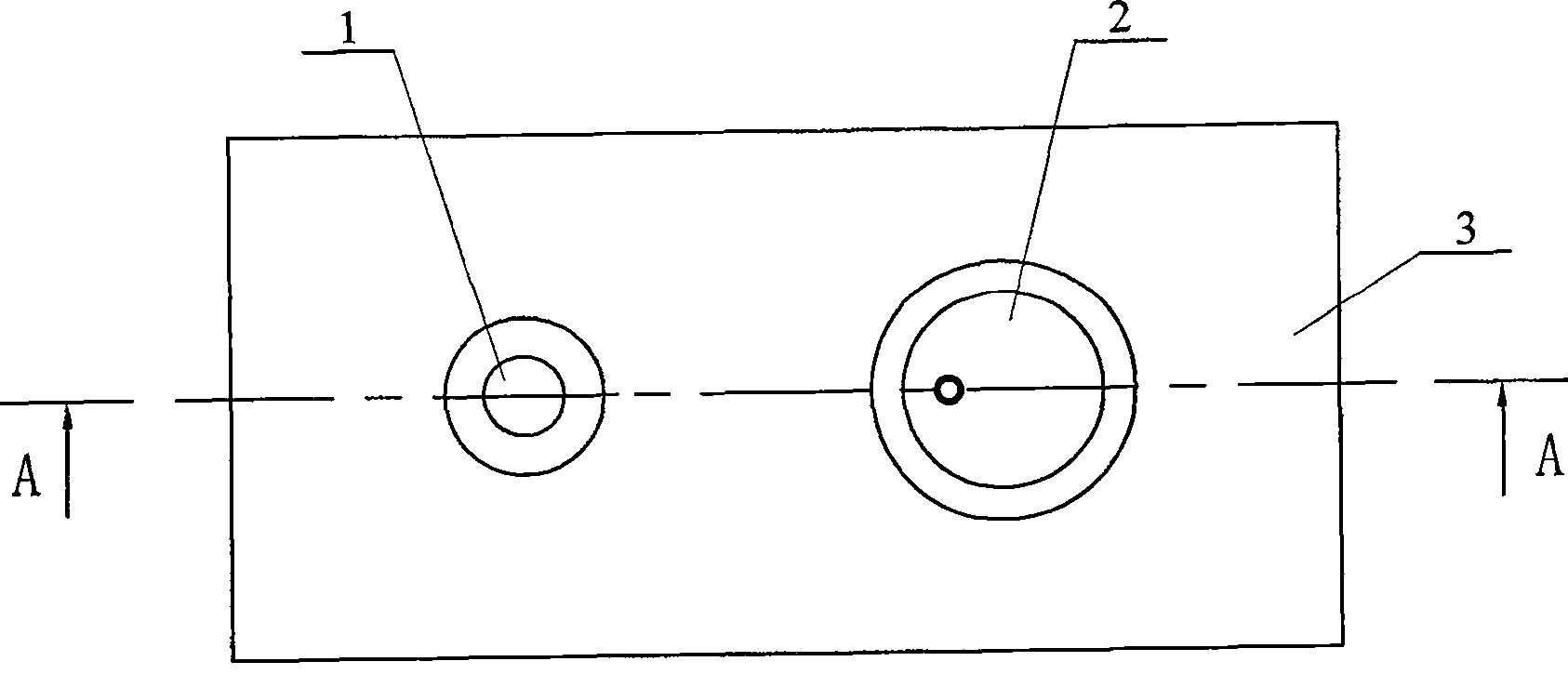
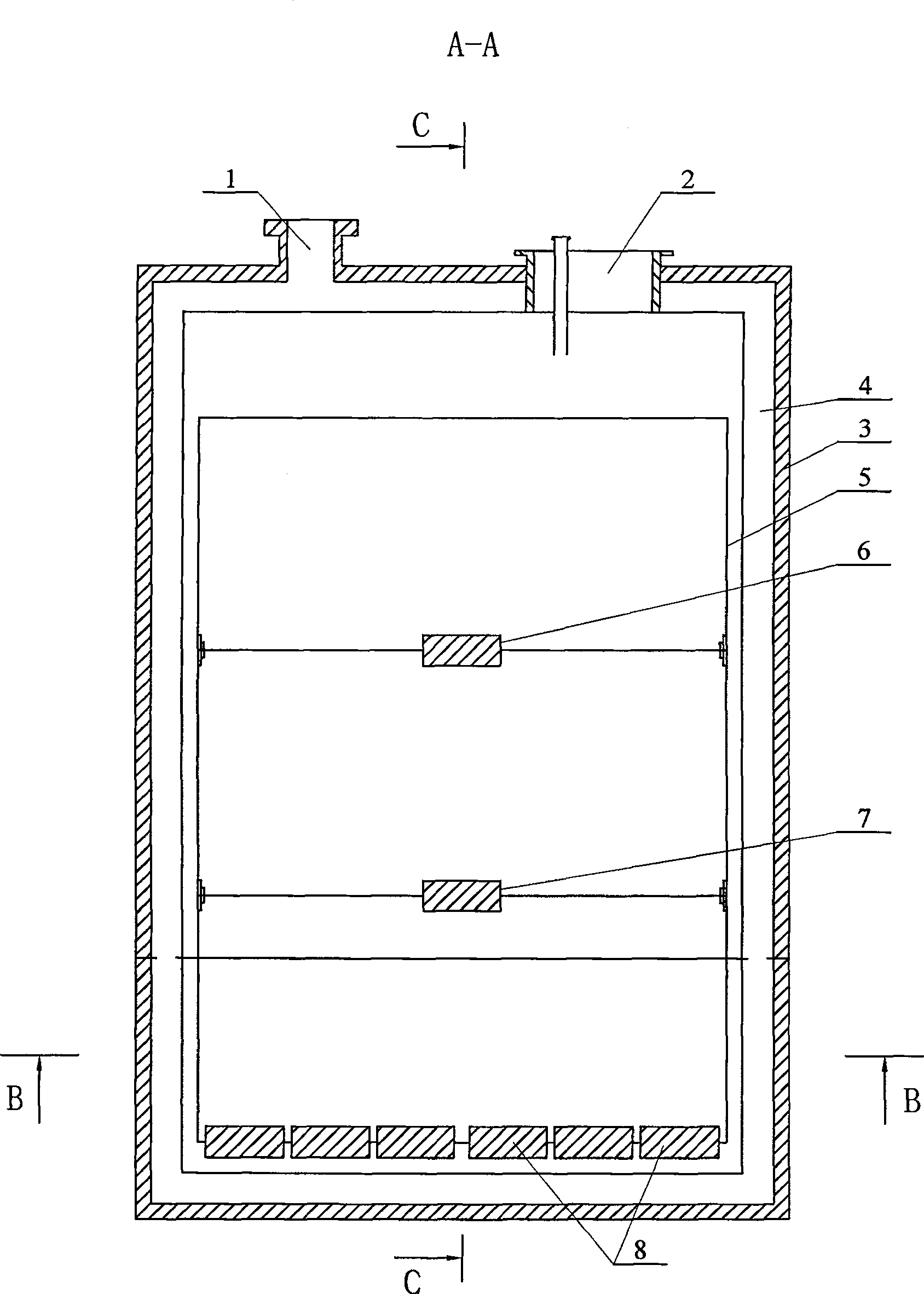
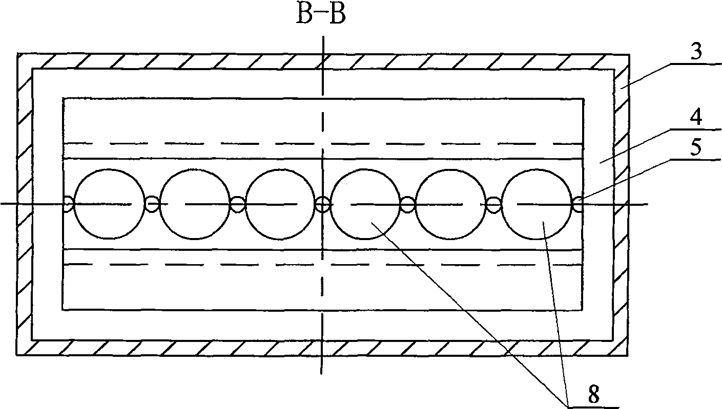
[0016] combine figure 1 , figure 2 , image 3 , Figure 4 As shown, the present invention is made up of non-magnetic Dewar shell 3, fixed support 5, main sensor 8 and reference sensor, and fixed support 5 is arranged in the non-magnetic Dewar shell 3 and between the non-magnetic Dewar shell 3 A vacuum heat insulation layer 4 is formed; the non-magnetic Dewar shell 3 is provided with an air suction port 1 communicating with the vacuum heat insulation layer 4; the non-magnetic Dewar shell 3 is also provided with a cable for connecting cables and filling liquid nitrogen Channel 2, the cable channel 2 communicates with the inner cavity of the fixed bracket 5; the main sensor 8 includes six SQUID sensors, and is fixed on the inner surface of the bottom of the fixed bracket 5 along the center line of the bottom surface of the fixed bracket 5; the reference sensor adopts a The SQUID sensor 7 is fixed in the middle of the axis of the fixed bracket 5, and the distance between the f...

Embodiment 2

[0020] combine figure 1 , figure 2 , image 3 , Figure 4 As shown, the difference between this embodiment and Embodiment 1 is that the reference sensor is composed of a first SQUID sensor 7 and a second SQUID sensor 6, and the second SQUID sensor 6 is arranged above the first SQUID sensor 7 And respectively fixed in the middle of the axis of the fixed bracket 5; the distance between the first SQUID sensor 7 and the main sensor 8 is 80-100 mm, and the distance between the second SQUID sensor 6 and the first SQUID sensor 7 is 60-80 mm. The six SQUID sensors in the main sensor 8 described in this embodiment and the two SQUID sensors in the reference sensor form a second-order gradiometer, which jointly realize the signal detection function and further enhance the effect of suppressing interference.


PUM


Abstract

The invention discloses a magnetocardiography probe, which solves the problem that a probe device needs to be horizontally and longitudinally moved time after time when finishing one time MCG base point measurement, thereby easily generating measurement error. The invention comprises a non-magnetic Dewar casing (3), a fixed support (5), a main sensor (8) and a reference sensor, wherein the fixed support (5) is arranged on the non-magnetic Dewar casing (3), a vacuum insulating layer (4) is formed between the non-magnetic Dewar casing (3) and the fixed support (5), the main sensor (8) comprises six SQUID sensors which are arranged side by side in line along the bottom center line of the fixed support (5), and the reference sensor is composed of one or two SQUID sensors. A first-order or second-order gradient meter is constituted by the main sensor (8) and the reference sensor to realize the function of signal detection. The probe device is moved on a direction to finish the measurement of 36 MCG base points when measuring the MCG. The invention has the advantages of reasonable structure and design, high measuring precision and simple operation.

Description

technical field [0001] The invention relates to a signal receiving device of biomagnetism detection equipment based on a high-temperature superconducting quantum interference device. Background technique [0002] The internationally recognized benchmark for the number of magnetocardiogram detection points is 36 points on the chest. The current number of magnetocardiographs is mostly 4 channels or 9 channels. It needs to move the probe device several times to detect the magnetic signal. Due to the layout of the sensor Limitation (4 channels is 2×2, 9 channels is 3×3), in actual application, the probe device needs to move horizontally and vertically for a corresponding number of times to complete a measurement, which is prone to measurement errors. Contents of the invention [0003] The technical problem to be solved by the present invention is to provide a signal receiving device based on a high-temperature superconducting quantum interferometer for biological magnetic dete...

Claims


Application Information

Patent Timeline
Patent Type & Authority Patents(China)
IPC IPC(8): A61B5/05
Inventor 涂凯王略米旺牛辉
Owner BEIJING SQUID QUANTUM TECH
Learn More