Backlight module

A backlight module and fluorescent tube technology, applied in optics, nonlinear optics, instruments, etc., can solve problems such as increased cost, poor connection, and impact on production yield and quality, and achieve the effect of saving production costs and speeding up the assembly process.

Active Publication Date: 2009-07-08
AU OPTRONICS CORP
View PDF8 Cites 0 Cited by
  • Summary
  • Abstract
  • Description
  • Claims
  • Application Information

AI Technical Summary

Problems solved by technology

[0007] It can be seen from the above description that the technical characteristics of the two existing backlight modules are similar, and no method for controlling the uniformity of the lamp current is considered in the design, which is not helpful for the brightness uniformity and image quality of the liquid crystal display.
In addition, multiple light tubes are directly connected to the circuit board, and the assembly needs to connect the light tubes and the circuit board by, for example, soldering, which will definitely hinder the simplification of the backlight module assembly process.
In addition, poor connections may occur during the assembly of the backlight module, thereby affecting the yield and quality of production and indirectly increasing production costs

Method used


Image

  • Backlight module
  • Backlight module
  • Backlight module

Examples


no. 1 example

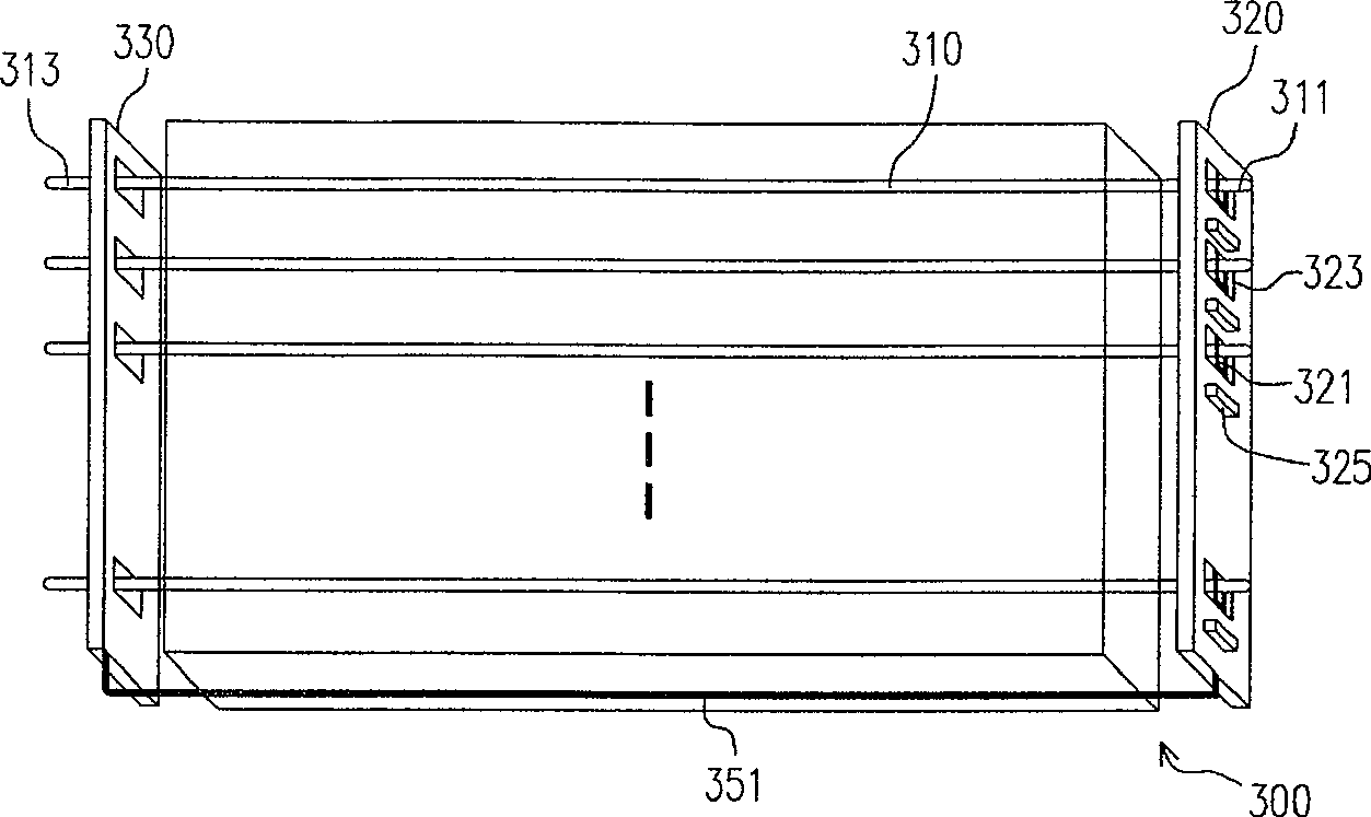
[0096] Figure 3A It is a three-dimensional schematic view of the first embodiment of the backlight module of the present invention. Please refer to Figure 3A , the backlight module 300 includes a plurality of lamp tubes 310 , a first circuit board 320 and a second circuit board 330 , wherein each lamp tube has a first electrode 311 and a second electrode 313 . The first circuit board 320 has a plurality of first conductive clips 321 , and the first conductive clips 321 hold the first electrode 311 . The second circuit board 330 is electrically connected to the second electrode 313 and the first circuit board 320 . In addition, the first circuit board 320 is disposed on one side (eg, the right side) of the backlight module 300 , and the second circuit board 330 is disposed on the other side (eg, the left side) of the backlight module 300 .

[0097] In this embodiment, the lamp 310 can be a CCFL, a Hot Cathode Fluorescent Lamp (HCFL) or an External Electrode Fluorescent Lam...

no. 2 example

[0109] Figure 5 It is a three-dimensional schematic view of the second embodiment of the backlight module of the present invention. This embodiment is similar to the first embodiment, except that the current adjusting element 525 in the second embodiment has at least one set of clamping pins 525 a for clamping the first electrode 511 .

[0110] Please refer to Figure 5 , the backlight module 500 of this embodiment includes a plurality of lamp tubes 510 , a first circuit board 520 and a second circuit board 530 . Wherein, each lamp tube 510 has a first electrode 511 and a second electrode 513 . The first circuit board 520 has a plurality of current adjustment elements 525 , wherein each current adjustment element 525 has at least one set of clamping pins 525 a for clamping the first electrode 511 . The second circuit board 530 is electrically connected to the second electrode 513 , and the second circuit board 530 can be electrically connected to the first circuit board 52...

no. 3 example

[0114] This embodiment is similar to the first embodiment, but the difference is that the current adjustment element 325 described in the first embodiment is arranged on the first circuit board 320, while the current adjustment element 637 of this embodiment is arranged on the second circuit board 630 .

[0115] Figure 6A and 6B It is a schematic diagram of the second circuit board of this embodiment. Please refer to Figure 6A In this embodiment, the second circuit board 630 has a control circuit 631 , a second conductive clip 633 , a second opening 635 , a current adjusting element 637 and at least one transformer 639 . The current adjusting element 637 is electrically connected to the second electrode 613 of the light tube through the second conductive clip 633 .

[0116] Please refer to Figure 6B In addition to the second conductive clip 633 , the current adjusting element 637 can also directly clamp the second electrode 613 of the lamp tube 610 through at least one...


PUM


Abstract

The invention discloses a backlight module, which comprises a plurality of lamp tubes, a first circuit board and a second circuit board. Each lamp has a first electrode and a second electrode. The first circuit board has a plurality of first openings and first conductive clips, wherein the first electrode passes through the first holes and is clamped by the first conductive clips. In addition, a plurality of lamp current adjustment elements are arranged on the first circuit board, and the current adjustment elements are electrically connected to the first electrode through the first conductive clip. In the above-mentioned backlight module, using the first conductive clip or the clamping pin of the current adjustment element to fix the electrode of the lamp tube helps to speed up the assembly process of the backlight module.

Description

technical field [0001] The present invention relates to a backlight module, and in particular to a backlight module which utilizes a conductive clip or a clamp pin of a current adjustment element to fix lamp tube electrodes. Background technique [0002] Liquid Crystal Displays (LCDs) are widely used in daily life, and more and more attention has been paid to the stability of the optical performance and the lightness and thinness of the appearance design of the LCDs. Liquid crystal displays usually use cold cathode fluorescent lamps (Cold Cathode Fluorescent Lamp, CCFL) as the backlight source. When the size of the liquid crystal display becomes larger, the number of lamp tubes used will also increase. Therefore, multiple lamp tubes are connected in parallel (for example, mutually Arranged in parallel) the technology used came into being. [0003] However, since the difference of each lamp tube cannot be ignored, and the leakage current of each lamp tube is also different d...

Claims


Application Information

Patent Timeline
Patent Type & Authority Patents(China)
IPC IPC(8): G02F1/13357G02F1/133G09G3/34H05K1/00
Inventor 洪泓杰郑咏泽孙嘉宏李宗勋
Owner AU OPTRONICS CORP
Why Eureka
Try Eureka