Smoke removing, temp lowering, afterheat using and recovering system in arc furnace and its dust removing technology

A technology of recovery system and recovery method, which is applied in the waste heat recovery system and recovery field of the exhaust gas cooling in the electric arc furnace, can solve the problems such as easy condensation of dust bag, consumption of cooling water, easy blockage of dust and heat exchange, etc., to achieve reduction Cooling water volume and maintenance costs, reduce operating costs, and reduce the effect of water-cooled flue

Active Publication Date: 2009-07-15
无锡市东方环境工程设计研究所有限公司
View PDF1 Cites 3 Cited by
  • Summary
  • Abstract
  • Description
  • Claims
  • Application Information

AI Technical Summary

Problems solved by technology

There are many disadvantages in the above cooling methods: 1. Directly mixed with cold air cooling method: the air volume after cooling increases greatly, which needs to increase the initial investment and operating costs of system pipes, fans and motors, and dust collectors
2. Water-cooled flue cooling method: a large amount of cooling water is required for cooling; the flue is heavy; public and auxiliary facilities that need to occupy and configure cooling water
This method is only suitable for flue gas with a temperature above 500°C. Due to the limitation of the site, it is generally not possible to configure too many
3. Air-cooled cooling method of mechanical cooler: this method needs to increase the cooling fan; the cooling effect is poor
The temperature of the inlet flue gas should not be higher than 500°C, and the cooling range is limited; it is easy to block the ash, affect the heat transfer and cause the system to deteriorate
4. Spray cooling method: Consuming cooling water and increasing the water content in the flue gas will not only make the dust bag easy to condense, but also easily cause the bag to fail in hydrolysis
However, this type of boiler belongs to the partition heat exchange, the high-temperature ash-containing flue gas flows outside the heat exchange tube, and the steam-water mixture flows in the heat exchange tube
Once the heat exchange tubes under poor working conditions are damaged, the high-temperature flue gas will directly mix with the soda-water mixture, forcing production to be shut down for maintenance
In addition, in the actual operation of this type of boiler, failures such as ash blocking and low-temperature corrosion cannot be solved well, which affects the normal production of the enterprise.

Method used


Image

  • Smoke removing, temp lowering, afterheat using and recovering system in arc furnace and its dust removing technology
  • Smoke removing, temp lowering, afterheat using and recovering system in arc furnace and its dust removing technology
  • Smoke removing, temp lowering, afterheat using and recovering system in arc furnace and its dust removing technology

Examples


Embodiment 1

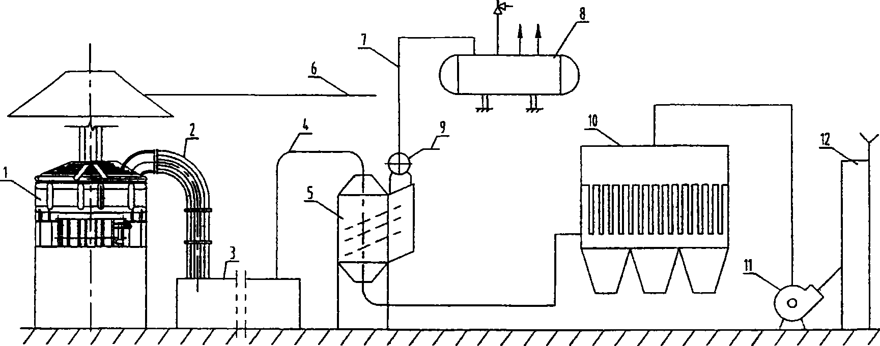
[0024] A 30t / h steelmaking electric arc furnace exhaust gas cooling waste heat utilization recovery dust removal system.

[0025] In the embodiment of the present invention, the electric arc furnace 1 is connected to the four-hole water-cooled sliding sleeve 2, the four-hole water-cooled sliding sleeve 2 is connected to the combustion settling chamber 3, the heat pipe steam generator 5 is connected to the combustion settling chamber 3 through the heat preservation pipe 4, and the heat pipe steam generator 5 passes through The pipeline is connected with the dust collector 10, and the dust collector 10 is connected with the main fan 11 through the pipeline, and the main fan 11 is connected with the exhaust tube 12. The heat pipe steam generator 5 is connected with the main water supply pipeline 9 , the main water supply pipeline 9 is connected with the main steam pipeline 7 , and the main steam pipeline 7 is connected with the steam accumulator 8 . The outer pipeline 6 is connec...

Embodiment 2

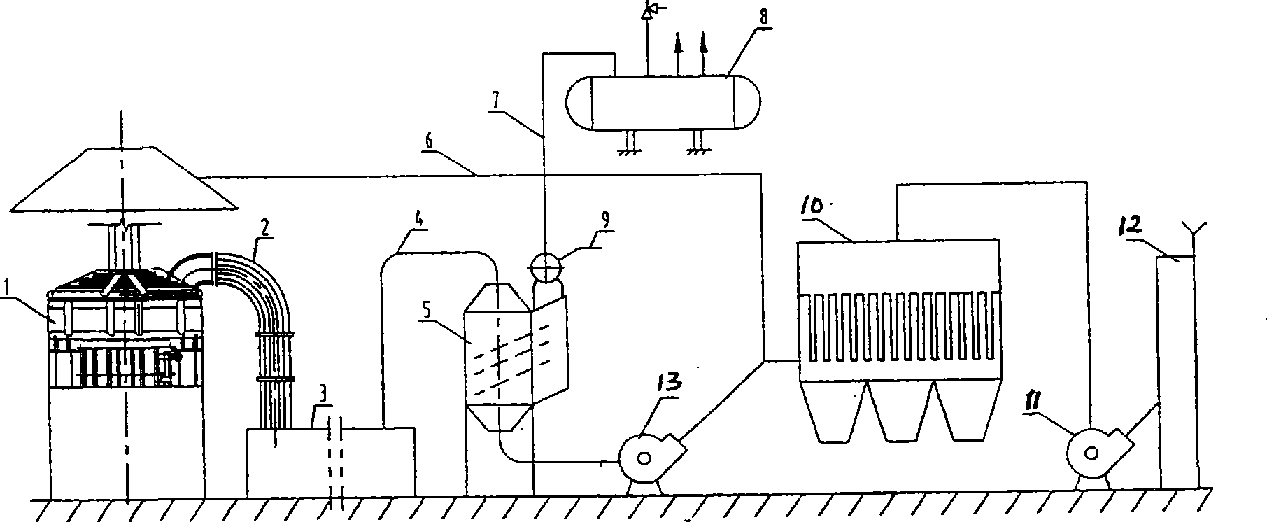
[0028] A 45t / h steelmaking electric arc furnace exhaust gas cooling waste heat utilization recovery dust removal system.

[0029] In the embodiment of the present invention, the electric arc furnace 1 is connected to the four-hole water-cooled sliding sleeve 2, the four-hole water-cooled sliding sleeve 2 is connected to the combustion settling chamber 3, the heat pipe steam generator 5 is connected to the combustion settling chamber 3 through the heat preservation pipe 4, and the heat pipe steam generator 5 passes through The pipeline is connected to the booster fan 13, and the booster fan 13 is connected to the dust collector 10 together with the outer discharge pipeline 6 connected to the top of the electric arc furnace 1. The dust collector 10 is connected to the main fan 11 through the pipeline, and the main fan 11 is connected to the exhaust tube 12. The heat pipe steam generator 5 is connected with the main water supply pipeline 9, and the main water supply pipeline 9 is ...

Embodiment 3

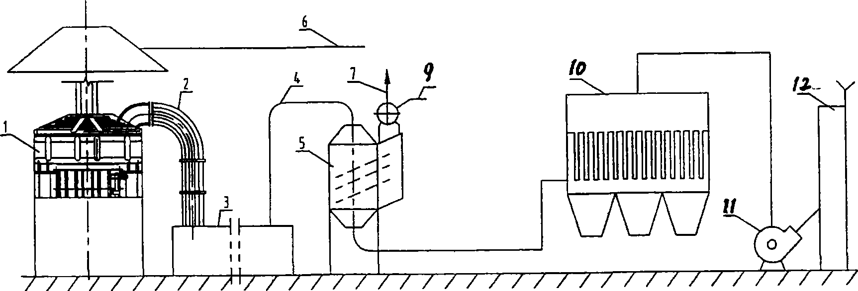
[0032] A 50t / h steelmaking electric arc furnace exhaust gas cooling waste heat utilization recovery dust removal system.

[0033] In the embodiment of the present invention, the electric arc furnace 1 is connected to the four-hole water-cooled sliding sleeve 2, the four-hole water-cooled sliding sleeve 2 is connected to the combustion settling chamber 3, the heat pipe steam generator 5 is connected to the combustion settling chamber 3 through the heat preservation pipe 4, and the heat pipe steam generator 5 passes through The pipeline is connected with the dust collector 10, and the dust collector 10 is connected with the main fan 11 through the pipeline, and the main fan 11 is connected with the exhaust tube 12. The main water supply pipeline 9 is connected to the heat pipe steam generator 5, and the main water supply pipeline 9 is connected to the main steam pipeline 7. The outer pipeline 6 is connected above the electric arc furnace 1 .

[0034] Such as image 3 As shown:...


PUM


Abstract

The invention relates to a smoke discharging and cooling afterheat recycling system and the dust removal technology in arc furnace. It connects the heat pipe steam generator with burning sedimentation chamber through insulated pipeline. The heat pipe steam generator connects to dust remover that connects the main blower fan. The main blower fan connects to exhaust mast. The smoke exhausts from arc furnace and coming into burning sedimentation chamber after mixing with cold wind in water cooling sliding sleeve. The smoke from the burning sedimentation chamber would come into the heat pipe steam generator. After taking dust removing to the smoke from the heat pipe steam generator, the main blower fan would press into exhaust mast and exhaust into atmosphere. The invention could effectively cool the high temperature smoke and recycle the heat energy in smoke, and improve the dust removing ability. It could lower running cost, and satisfy normal producing request.

Description

technical field [0001] The invention relates to an electric arc furnace exhaust gas cooling waste heat utilization recovery system and a recovery method thereof. Specifically, it can efficiently cool high-temperature flue gas, recover heat energy in the flue gas to the greatest extent, and improve dust removal ability, belonging to an electric arc furnace. Dust removal technology field. Background technique [0002] The flue gas exhausted from electric arc furnace steelmaking (discharged from the fourth hole or the second hole of the furnace cover) has a high temperature, generally around 1200°C, and must be cooled before dust can be removed. At present, the following cooling methods are usually used: direct mixing of cold air, water-cooled flue, mechanical cooler air cooling, spray cooling, etc. There are many shortcomings in the above-mentioned cooling methods: 1. Directly mixed with cold air cooling method: the air volume after cooling increases greatly, and the initial ...

Claims


Application Information

Patent Timeline
Patent Type & Authority Patents(China)
IPC IPC(8): F27D17/00
CPCY02P10/25
Inventor 郑岩谈庆
Owner 无锡市东方环境工程设计研究所有限公司
Why Eureka
Try Eureka