Pipe-line design for fully using space of integrated fuel cell pile
A fuel cell stack and integrated technology, applied to fuel cell parts, fuel cells, battery electrodes, etc., can solve the problems of single cell performance differences, waste, large pressure loss, etc., and achieve the effect of compact structure and easy installation
- Summary
- Abstract
- Description
- Claims
- Application Information
AI Technical Summary
Problems solved by technology
Method used
Image


Examples
Embodiment 1
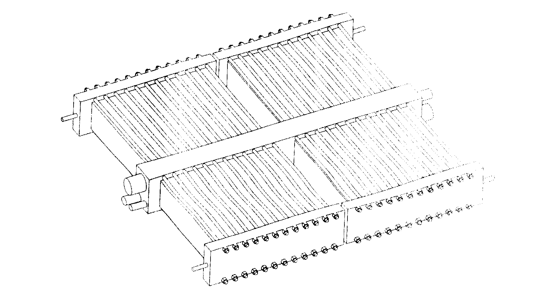
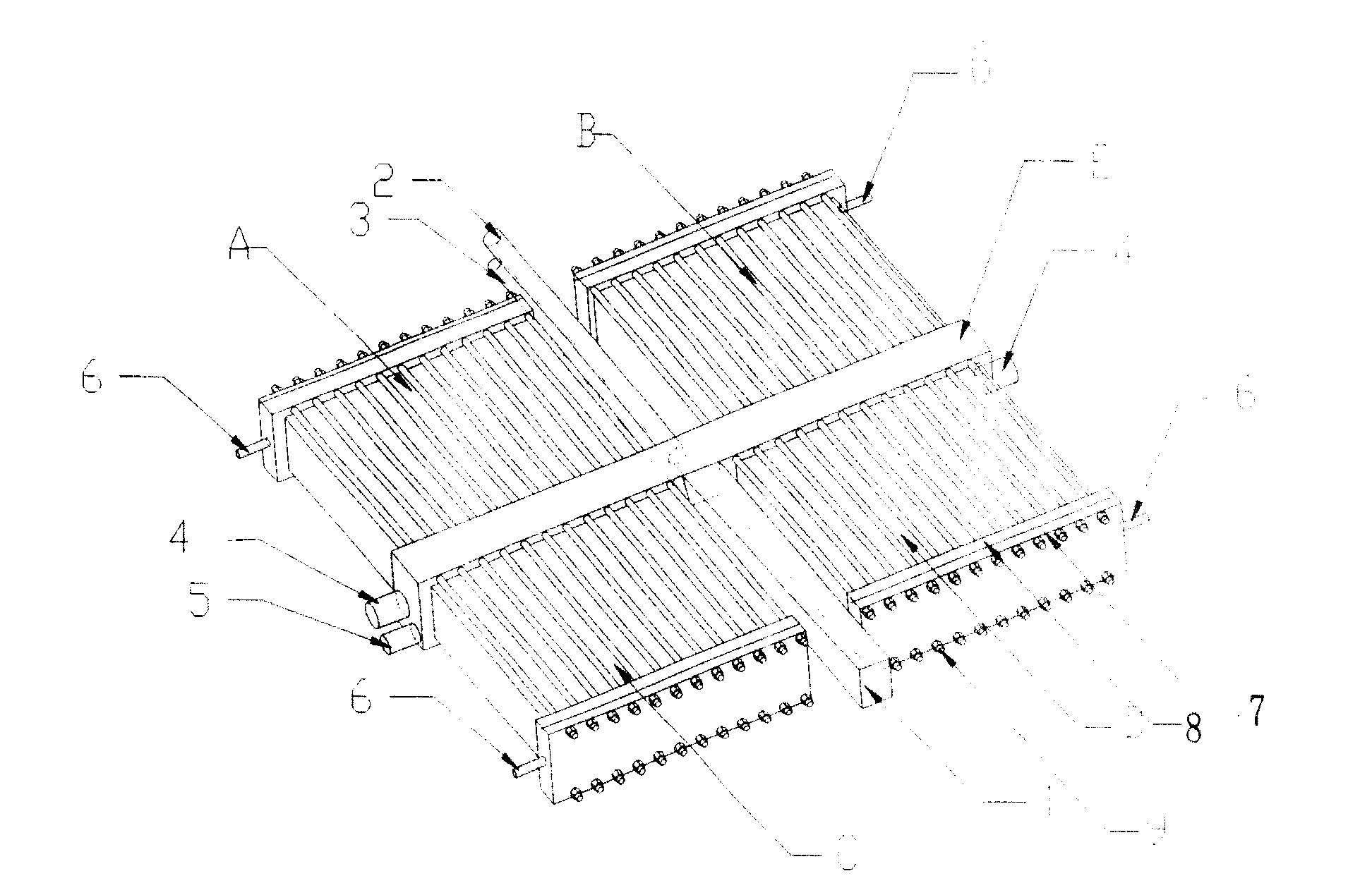
[0035] Such as figure 2 As shown, a 50KW ~ 100KW pipeline design that makes full use of the space formed between the integrated fuel cell stacks, which includes four groups of fuel cell stacks A, B, C, D (where A, C groups and B, D groups left and right symmetrical) and a central collector plate E, four groups of fuel cell stacks are arranged on both sides of the central collector plate and clamped and share the central collector plate, and the end plate 7 is clamped and fixed by the screw rod 9 to form a When the integrated fuel cell is integrated and packaged, a gap perpendicular to the central collector plate is formed, and the air inlet pipeline 1, the hydrogen gas inlet pipeline 3, and the cooling fluid pipeline 3 are respectively connected from both sides of the central collector plate gap to the On the central collector plate, the air outlet pipeline 4 is drawn from both ends of the central collector plate, and the front of the end plate 7 is provided with a collector ...
Embodiment 2
[0039] Such as image 3 As shown, a 50KW ~ 100KW pipeline design that fully utilizes the space of the integrated fuel cell stack, which includes four groups of fuel cell stacks A, B, C, D (where A, C groups are symmetrical to B, D groups) and A central collector plate E, four groups of fuel cell stacks are arranged on both sides of the central collector plate and clamped and share the central collector plate, and the end plate 7 is clamped and fixed by the screw rod 9 to fix the battery stack, thereby forming an integrated fuel cell , when performing integrated packaging, a gap perpendicular to the central collector plate is formed, and the air inlet pipeline 1, the hydrogen inlet pipeline 3, and the cooling fluid pipeline 3 are respectively connected to the central collector plate from both sides of the gap, and the air outlet Pipeline 4 is led out from both ends of the central collector plate, and a collector plate 8 is provided in front of the end plate 7. The hydrogen outl...
Embodiment 3
[0043] Such as Figure 4 As shown, a 50KW ~ 100KW pipeline design that fully utilizes the space of the integrated fuel cell stack, which includes four groups of fuel cell stacks A, B, C, D (where A, C groups are symmetrical to B, D groups) and A central collector plate E, four groups of fuel cell stacks are arranged on both sides of the central collector plate and clamped and share the central collector plate, and the end plate 7 is clamped and fixed by the screw rod 9 to fix the battery stack, thereby forming an integrated fuel cell , when performing integrated packaging, a gap perpendicular to the central collector plate is formed, and the air inlet pipeline 1, the hydrogen inlet pipeline 3, and the cooling fluid pipeline 3 are respectively connected to the central collector plate from both sides of the gap, and the air outlet Pipeline 4 is led out from both ends of the central collector plate. A collector plate 8 is provided in front of the end plate 7. The hydrogen outlet ...
PUM
 Abstract
Description
Claims
Application Information
 - R&D
- Intellectual Property
- Life Sciences
- Materials
- Tech Scout
- Unparalleled Data Quality
- Higher Quality Content
- 60% Fewer Hallucinations
Browse by: Latest US Patents, China's latest patents, Technical Efficacy Thesaurus, Application Domain, Technology Topic, Popular Technical Reports.
© 2025 PatSnap. All rights reserved.Legal|Privacy policy|Modern Slavery Act Transparency Statement|Sitemap|About US| Contact US: help@patsnap.com