Device comprising two mutually adapted impedances for the purpose of power transmission

A device, a technology of reactance value, applied in the field of devices including two mutually adaptive impedances for power transmission purposes, to achieve the effect of low power reflection level, improved power transmission, and good power transmission

Inactive Publication Date: 2009-08-05
NXP BV
View PDF2 Cites 0 Cited by
  • Summary
  • Abstract
  • Description
  • Claims
  • Application Information

AI Technical Summary

Problems solved by technology

[0006] In the known data carriers, there is a problem that, irrespective of whether there is an adaptation of the two impedances to each other, said adaptation being considered to facilitate the power transfer between the antenna structure and the circuit, the two impedances At least one of the impedances in has, with respect to its reactance, in fact a difference in reactance value from the nominal reactance value suitable for power transfer between the antenna structure and the circuit

Method used


Image

  • Device comprising two mutually adapted impedances for the purpose of power transmission
  • Device comprising two mutually adapted impedances for the purpose of power transmission
  • Device comprising two mutually adapted impedances for the purpose of power transmission

Examples


Embodiment Construction

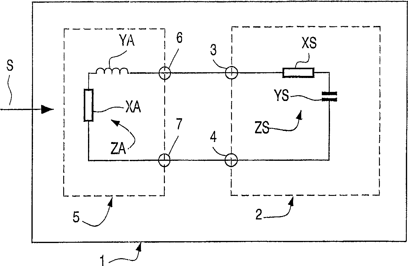
[0022] figure 1 Shown in is a device 1 for processing a signal S, this device 1 is formed by a data carrier 1 for contactless communication, the data carrier 1 can take a transponder, or an electronic ticket, or a smart tag, or a chip card form.

[0023] The signal S is realized by means of a carrier signal with a carrier frequency, which is used in communication equipment (in figure 1 Not shown in ) and the communication of information between the data carrier. The carrier signal used to communicate information is in the present case amplitude modulated as a function of said information. However, it should be appreciated at this point that other types of modulation can also be performed, eg phase modulation or frequency modulation. The signal S emitted by the communication device with a defined power can also be used to supply the data carrier 1 with electrical power. Therefore, the distance between the data carrier and the communication device available for communication...


PUM


Abstract

A device (1) for processing a signal (S) having an antenna structure (5) arranged to transmit a signal (S) to a circuit (2), the antenna structure (5) having at least An antenna structure terminal (6, 7), the antenna structure terminal is intended to connect the antenna structure (5) to the circuit (2), and the antenna structure (5) has an antenna structure impedance (ZA) at the antenna structure terminal (6, 7) ; circuit (2), circuit (2) has at least one circuit terminal (3, 4), circuit (2) has circuit impedance (ZS) at circuit terminal, circuit (2) is connected to antenna structure terminal (6, 4) at circuit terminal 7) for power transfer between the antenna structure (5) and the circuit (2) with a signal (S), wherein at least one of the two impedances (ZA, ZS) is, in terms of its reactance (YA, YS) In terms of, has a nominal reactance value (Y NOM ), the nominal reactance value is suitable for transferring power between the antenna structure (5) and the circuit (2), one of the two impedances (ZA, ZS) has a resistance (XA, XS), The resistors (XA, XS) have a resistance value (X) greater than a nominal resistance value (X) suitable for transferring power between the antenna structure (5) and the circuit (2). NOM ), and less than the maximum resistance value (X MAX ).

Description

technical field [0001] The invention relates to a device for processing signals, said device having an antenna structure arranged to transmit a signal, said antenna structure having at least one antenna structure terminal intended to connect the antenna structure to a circuit, and the antenna structure has an antenna structure impedance at the antenna structure terminals, said device has said circuit, said circuit has at least one circuit terminal, said circuit has a circuit impedance at said circuit terminals, and Said circuit is connected at said circuit terminal to the antenna structure terminal for power transfer between the antenna structure and the circuit using said signal, wherein at least one of the two impedances, in terms of its reactance , having a reactance value different from the nominal reactance value suitable for transferring power between the antenna structure and the circuit. [0002] The invention further relates to an antenna structure for a device for p...

Claims


Application Information

Patent Timeline
Patent Type & Authority Patents(China)
IPC IPC(8): H03H7/38G06K19/07H02J17/00H04B1/18H04B1/59
CPCH03H7/38G06K19/07777G06K19/0701G06K19/0723
Inventor R·布兰德尔
Owner NXP BV
Why Eureka
Try Eureka