Internal combustion engine

A technology for internal combustion engines and crankshafts, applied in the field of internal combustion engines, can solve the problems of engine efficiency reduction, loss, and engine work efficiency reduction, etc.

Inactive Publication Date: 2009-02-25
斯库利·TH·夫捷尔斯特
View PDF0 Cites 0 Cited by
  • Summary
  • Abstract
  • Description
  • Claims
  • Application Information

AI Technical Summary

Problems solved by technology

[0002] In an ordinary internal combustion engine, the mixture gas (load) is pre-ignited before or after the piston reaches the top dead center, thereby producing a reaction force acting on the crankshaft rotation process or acting on the engine at an unsuitable angle. The force of the crank tip that rotates the crankshaft, thereby reducing the efficiency and unnecessary loss of the piston, piston rod, crank tip, crankshaft, and the entire engine, reducing the engine's working efficiency

Method used


Image

  • Internal combustion engine
  • Internal combustion engine
  • Internal combustion engine

Examples


Embodiment Construction

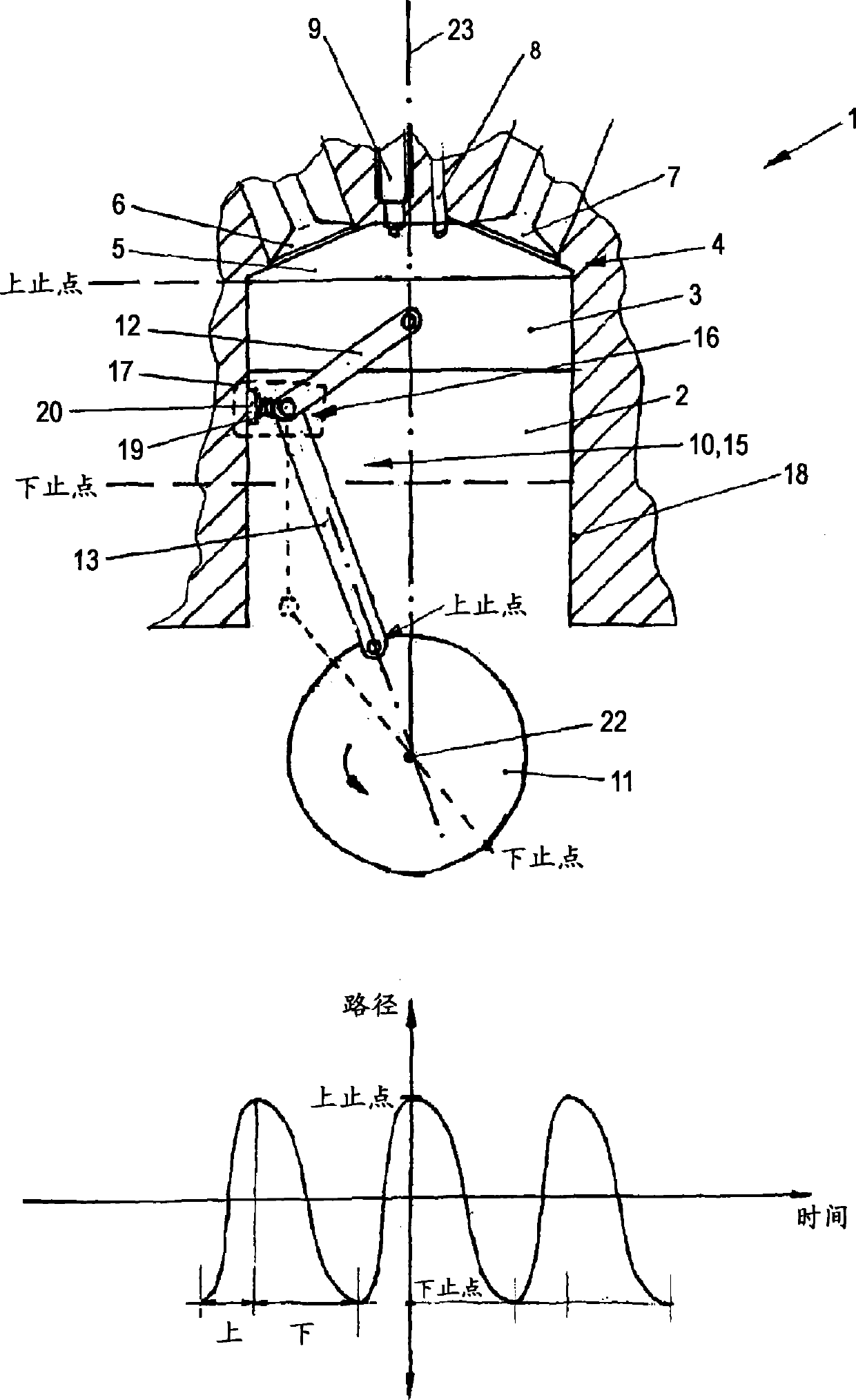
[0023] figure 1 A sectional view of a cylinder 2 of an internal combustion engine 1 in a first embodiment of the invention is shown. A piston 3 that can slide up and down in the cylinder 2 is arranged in the cylinder 2 . The piston 3 and the upper end of the cylinder 2 and the cylinder head 4 form a combustion chamber 5 . The cylinder head 4 is provided with an intake valve 6 and an exhaust valve 7 for introducing air and exhausting exhaust gas, a nozzle 8 for injecting fuel, and a spark plug 9 for igniting a mixture gas.

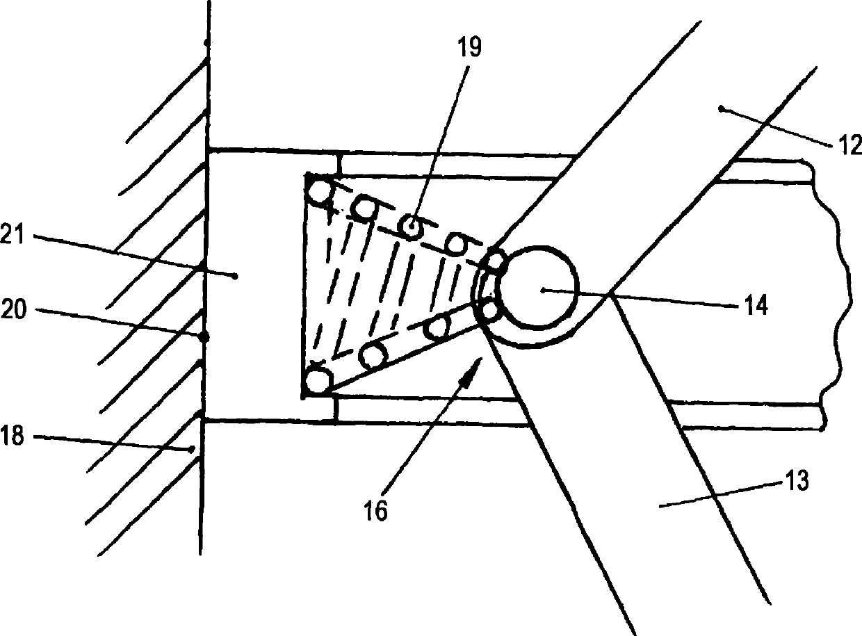
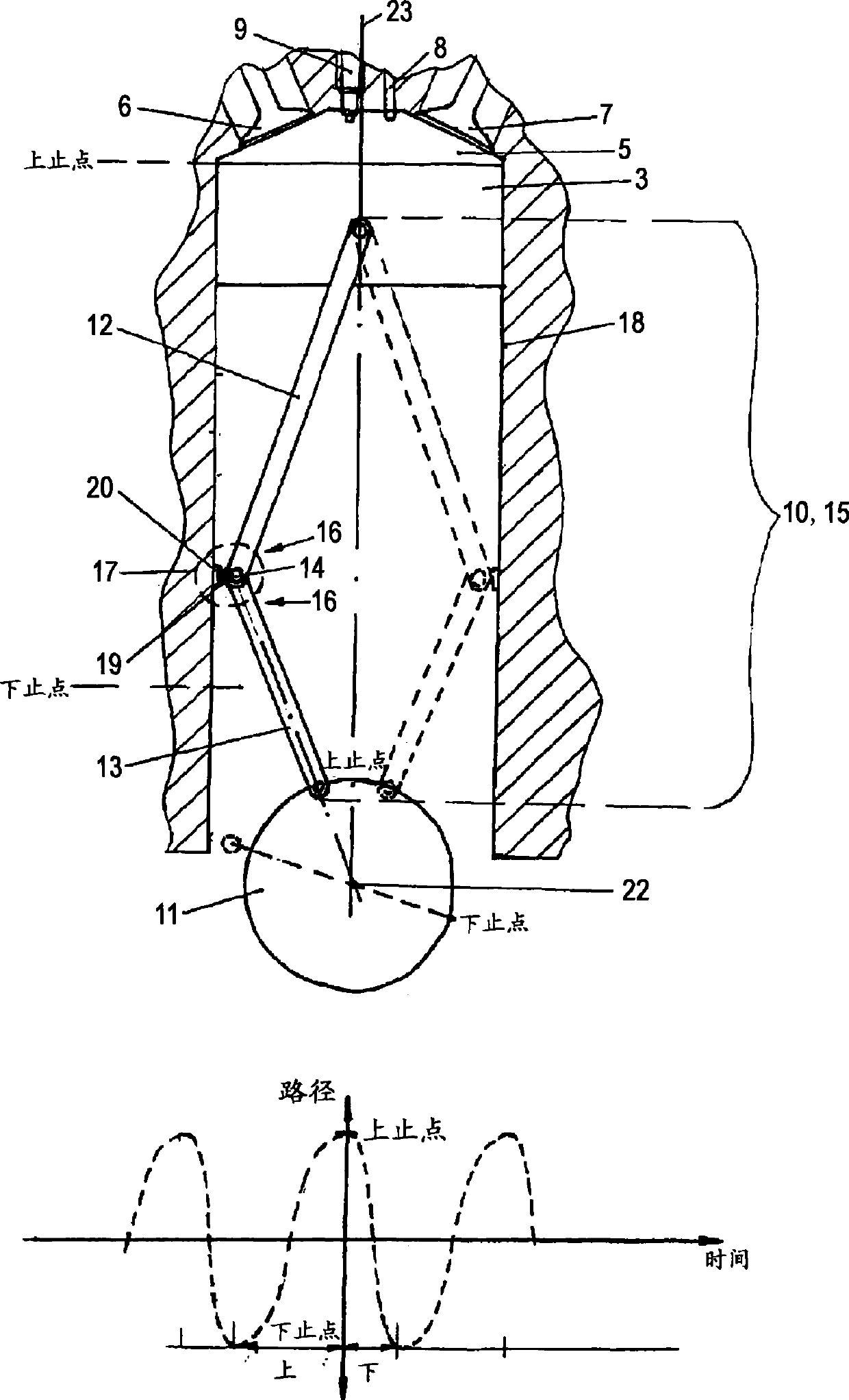
[0024] The piston 3 transmits the load generated by the gas mixture explosion to the crankshaft 11 through the adjusting device 10 . In this specific embodiment, the adjusting device 10 comprises a piston rod assembly 15 having two piston rods 12 , 13 articulated to each other via a rotating shaft 14 . The first piston rod 12 in this specific embodiment is hingedly connected with the piston 3 . Alternatively, the rod 12 can also be fixed on or connected...


PUM


Abstract

The invention is to improve the efficiency and/or the compression of an internal combustion engine having at least one cylinder (2), at least one piston (2) which moves up and down inside the cylinder (2), and at least one crankshaft (11). This object is achieved by an internal combustion engine of the above mentioned kind in which a modifier device (10) is provided between the piston (3) and the crankshaft (11) which affects the movement of the piston (3) such that the downward cycle differs from the upward cycle. The modifier device (3) includes a piston rod component (15) having at least two pivot joint levers (12, 13), one of which is connected with the piston (3), while the other one (13) is connected with the crankshaft (11) via the pivot.

Description

technical field [0001] The invention relates to an internal combustion engine having at least one cylinder, a crankshaft and a piston that can move up and down in the cylinder. Background technique [0002] In an ordinary internal combustion engine, the mixture gas (load) is pre-ignited before or after the piston reaches the top dead center, thereby producing a reaction force acting on the crankshaft rotation process or acting on the engine at an unsuitable angle. The force of the crank tip that rotates the crankshaft, thereby reducing the efficiency and unnecessary loss of the piston, piston rod, crank tip, crankshaft and the entire engine, and reducing the working efficiency of the engine. On the other hand, the working efficiency of the internal combustion engine is also affected by the pressure in the combustion chamber. Insufficient engine operating efficiency must be compensated by higher fuel consumption. Contents of the invention [0003] It is therefore the obje...

Claims


Application Information

Patent Timeline
Patent Type & Authority Applications(China)
IPC IPC(8): F02B75/32F02B41/04
CPCF02B41/04F02B75/32Y02T10/14F02B75/048Y02T10/12
Inventor 斯库利·TH·夫捷尔斯特斯库利·Th·夫捷尔斯特
Owner 斯库利·TH·夫捷尔斯特
Why Eureka
Try Eureka