a wrench

A wrench and electric wrench technology, applied in the field of wrenches, can solve problems such as limited adjustment angle, inability to adapt to knife gate bolt tightening, inability to complete knife gate bolt tightening work, etc., to increase safety factor, high tightening efficiency, and strong practicability Effect

Active Publication Date: 2021-03-30
国网河南省电力公司超高压公司 +1
View PDF9 Cites 0 Cited by
  • Summary
  • Abstract
  • Description
  • Claims
  • Application Information

AI Technical Summary

Problems solved by technology

The lower end of the second sleeve is fixedly connected with the insulating rod, the lower end of the first sleeve is connected with the upper end of the second sleeve in rotation, and the first sleeve and the second sleeve are relatively fixed by claw screws, and the second sleeve is relatively fixed. The left and right sides of the sleeve head are respectively provided with left and right through holes, and the two first screws pass through the left and right through holes respectively, and the left and right relative positions of the first sleeve head are fine-tuned through the first screws to drive the adjustment of the electric wrench. The relative position of the left and right, the invention can fine-tune the angle between the wrench and the insulating rod, and accurately adjust the angle between the electric wrench and the insulating rod, but the angle of adjustment is limited, and it cannot adapt to the large difference in azimuth and orientation. Tightening of different knife brake bolts
[0004] The Chinese invention patent application with the publication number CN109093550A discloses a new type of electric wrench for fastening the bolts of the drainage plate, including a fixed bolt mechanism that is stuck on both sides of the bolt and can prevent the nut from rotating, and is used to drive the nut to rotate so that the nut The electric wrench screwed on the drainage plate, the insulating rod used to realize the remote insulation operation, and the pneumatic switch used to drive the electric wrench to work, wherein the fixing bolt mechanism is installed directly above the electric wrench, and the insulating rod is installed on the electric wrench Underneath, the pneumatic switch is electrically connected with the electric wrench, which can realize the long-distance manual and electric fastening of the drainage plate bolts without power failure, but the socket head of the electric wrench is vertically upward, which cannot complete the knife lock bolts. tightening work

Method used


Image

  • a wrench
  • a wrench
  • a wrench

Examples


Embodiment 1

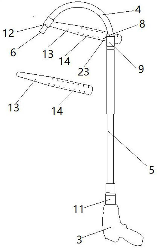
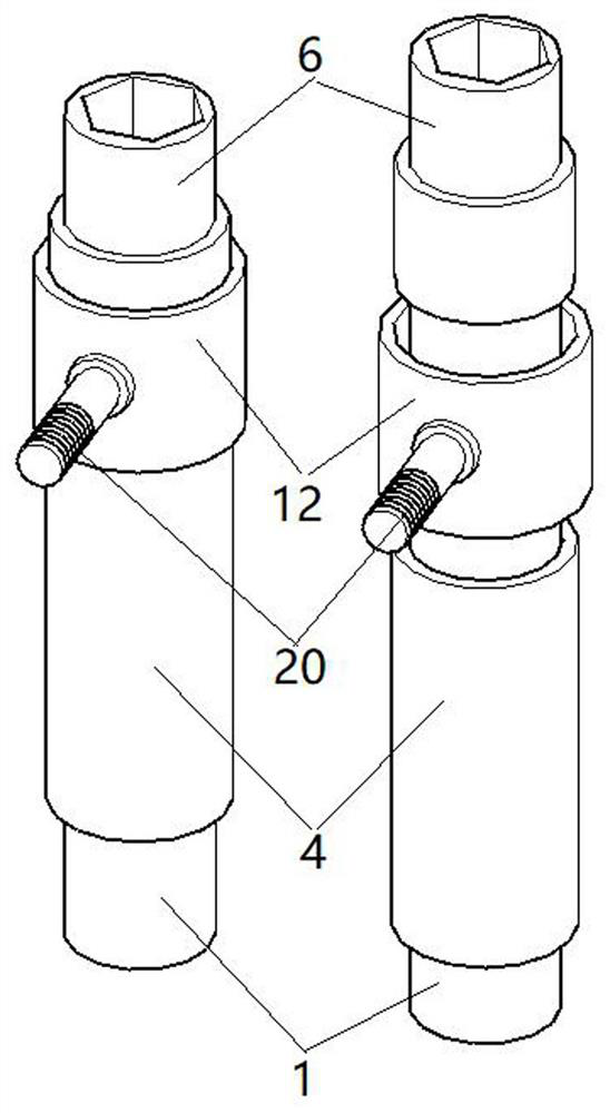
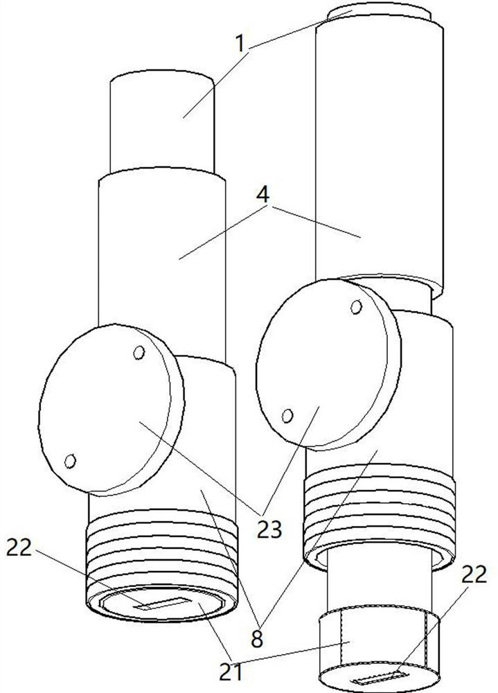
[0037] Such as Figure 1-6 Shown is the first embodiment of the present invention, an electric wrench, including a flexible shaft 1, a transmission shaft 2 and an electric wrench 3, the transmission shaft 2 is a steel round shaft, the flexible shaft 1 is sleeved with a sleeve 4, and the sleeve Tube 4 is an insulating hose made of rubber, such as figure 2 As shown, the sleeve head 6 is installed on the top of the flexible shaft 1 by welding or other means. The sleeve head 6 is a hexagonal socket head. You can prepare several more flexible shafts. The top of 4 press-fits the limit tube 12, the limit tube 12 is sleeved on the tail end of the sleeve head 6, and the bottom end of the flexible shaft 1 is welded with a steel cylinder-21, such as image 3 As shown, the center of the lower part of cylinder one 21 is cut with a cutting machine to form a keyway 22, cylinder one 21 and sleeve head 6 can be used as a limit assembly to prevent flexible shaft 1 from detaching from sleeve 4...

Embodiment 2

[0040] Such as Figure 7 Shown is the second embodiment of the present invention, the outer peripheral surface of cylinder one 21 is welded with bearing one 30, and the outer ring peripheral surface of bearing one 30 is welded in joint one 8; the outer peripheral surface of cylinder two 24 is welded with bearing two 31, bearing two 31 The outer peripheral surface of the outer ring is welded in joint two 9; the outer peripheral surface of cylinder three 26 is installed with welding bearing three 32 by means of glue, etc., the outer ring peripheral surface of bearing three 32 is welded in joint four 11, bearing one 30, bearing two 31 And bearing three 32 are tapered roller bearings.

Embodiment 4

[0044] Such as Figure 9 Shown is the fourth embodiment of the present invention, which is different from the first embodiment in that, due to the relatively high position of the equipment, two insulating rods 5 with drive shafts 2 inside need to be spliced ​​together. The bottom end of transmission shaft 2 is welded with cylinder 3 26, the bottom end of cylinder 3 26 is welded with hexagonal rod 2 27, the top of drive shaft 7 located below is welded with cylinder 2 24, and the top surface of cylinder 2 24 is welded with a hexagonal sleeve matching hexagonal rod 2 27 Two 28, crimp joint four 11 at the bottom end of insulating rod 5 located above, crimp joint five 33 at the top of insulating rod 5 located below, joint five 33 is exactly the same as joint three 10, when splicing, insert hexagonal pole two 27 into the hexagon In the sleeve two 28, the joint five 33 is screwed into the joint three 10.


PUM


Abstract

The invention discloses a spanner. The spanner comprises a flexible shaft, a transmission shaft and an electric spanner. The flexible shaft is sleeved with a sleeve, the sleeve is a hose, a first limiting assembly for preventing the flexible shaft from disengaging from the sleeve is arranged on the flexible shaft, the transmission shaft is sleeved with an insulating rod, a second limiting assemblyfor preventing the transmission shaft from disengaging from the sleeve is arranged on the transmission shaft, a sleeve head is arranged at one end of the flexible shaft, the other end of the flexibleshaft is connected with the transmission shaft, the other end of the transmission shaft is connected with an output shaft of the electric spanner, the tail of the sleeve head is sleeved with one endof the sleeve, the other end of the sleeve is connected with the top end of the insulating rod, disconnector bolts can be tightened under the conditions of ground potential and uninterrupted power supply, the safety is good, and the working efficiency is high.

Description

technical field [0001] The invention relates to the technical field of electrical equipment, in particular to a wrench. Background technique [0002] The open isolating switch is an important switchgear in the electrical system of the substation. After the knife switch of the isolating switch is loose, it will cause the knife switch to heat up, which in turn will cause the isolating switch to heat up. circuit, causing the circuit breaker to trip, thereby affecting the stable operation of the power grid. Therefore, when the isolating switch heats up, it is necessary to use an effective special tool that can be used on site to tighten the knife bolt in time. [0003] The Chinese invention patent with the notification number CN105313063B discloses a special insulating sleeve based on an electric wrench, including a first sleeve and a second sleeve, and the upper end of the first sleeve is fixed with the cooperation of the electric wrench. The lower end of the second sleeve is ...

Claims


Application Information

Patent Timeline
Patent Type & Authority Patents(China)
IPC IPC(8): B25B21/00B25B23/00
CPCB25B21/002B25B23/0028
Inventor 王长义麻森张海涛李纯刘春李洪波张庆军胡润阁孟卓伦张宏
Owner 国网河南省电力公司超高压公司
Why Eureka
Try Eureka