
Supercritical dyeing pot

A dyeing tank and supercritical technology, which is applied in dyeing, textiles and papermaking, liquid/gas/steam textile material processing, etc., can solve problems such as uneven dyeing, improve dyeing effect, avoid leakage, and ensure stability Effect

Inactive Publication Date: 2009-08-19
CHINA TEXTILE ACAD JIANGNAN BRANCH
View PDF5 Cites 2 Cited by
  • Summary
  • Abstract
  • Description
  • Claims
  • Application Information

AI Technical Summary

Problems solved by technology

[0003] Another example is that Chinese patent application 200510136782.2 relates to setting columns or inner tubes in the dyeing tank. The main disadvantage is that because the columns or inner tubes for stacking yarns or fabrics in the tank are fixed, the dyed materials It is also fixed and static, so it is easy to cause uneven dyeing inside and outside the whole roll of stacked materials

Method used


Image

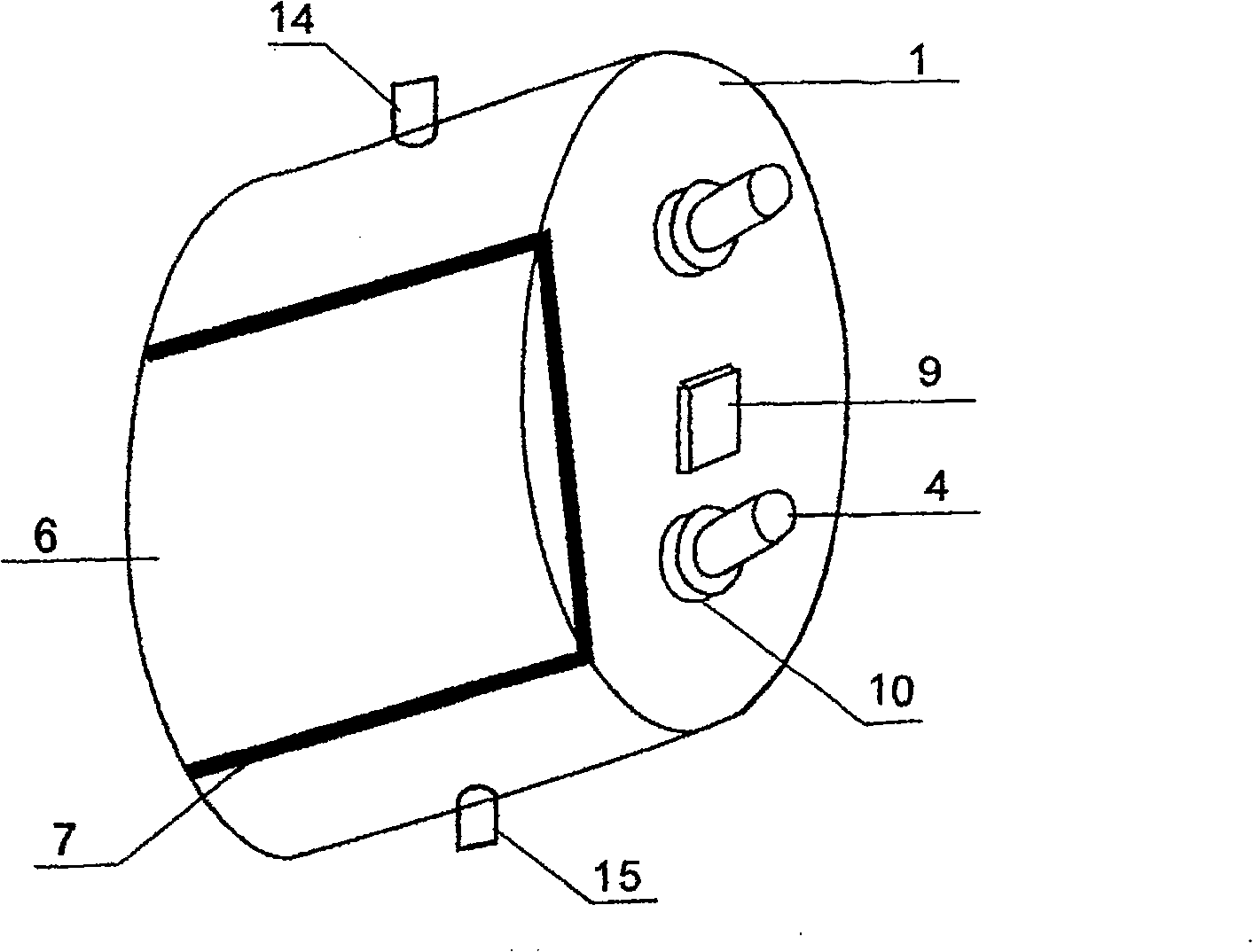
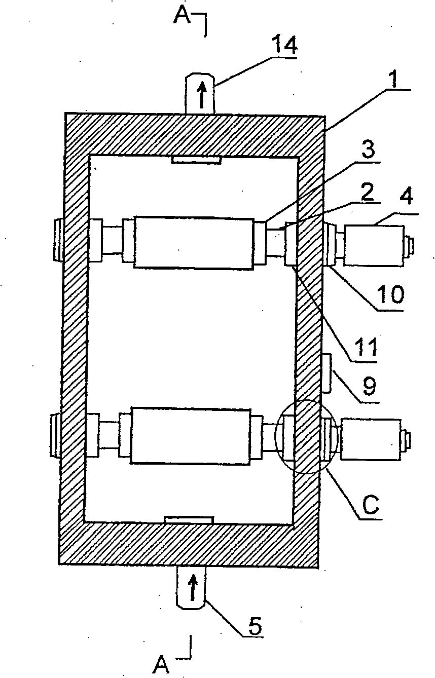
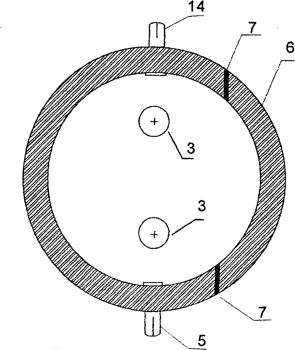
  • Supercritical dyeing pot
  • Supercritical dyeing pot
  • Supercritical dyeing pot

Examples


Embodiment 1

[0024] Embodiment 1, fabric dyeing:

[0025] 1. Fabric upper shaft: Open the cover 6 of the dyeing tank with a tool, fix the roll 3 on the transmission shaft 2, wind the polyester fabric of a certain width and length onto the roll 3 of a transmission shaft 2;

[0026] 2. Transmission shaft fixing: There are two transmission shafts 2, which are respectively fixed. A transmission shaft 2 is fixed at the bushing 8 of the inner wall of the dyeing tank, and there is no roll cloth on the winding roller 3 of the other transmission shaft 2, and this transmission shaft 2 is fixed at another bushing;

[0027] 3. Leading cloth: also known as threading cloth, lead the cloth head on the cloth roll 3 to another empty roll 3 and fix it, the empty roll 3 is active, and the cloth roll 3 is passive;

[0028] 4. Test run: Turn on the external motor 4 and the magnetic coupler 10, the transmission shaft 2 and the winding roller 3 are tightly attracted to the inner wall of the tank body 1 along wi...

Embodiment 2

[0031] Embodiment 2, skein dyeing:

[0032] 1. Skein upper shaft: put a certain amount of polyester blended yarn on the winding roller 3 outside the two transmission shafts 2;

[0033] 2. Fixing of the yarn shaft: two winding rollers 3 are respectively fixed at the bushing 8 on the inner wall of the tank body 1, one winding roller 3 is active, and the other winding roller 3 is passive;

[0034] 3. Test run: open the motor 4 and the magnetic coupler 10 outside the tank 1, the transmission shaft 2 is attracted to the inner wall of the tank 1 with the permanent magnet 11, adjust the electromagnetic torque of the magnetic coupler 10, and adjust the metering device 9 to normal status;

[0035] 4. Airtight, enter the supercritical state for dyeing, according to the preset time, manual or automatic rewinding;

[0036] 5. Shaft output: After the dyeing is completed, the dyeing tank can be opened and the shaft is output when the pressure is released and the temperature is lowered to ...


PUM


Abstract

The present invention is one supercritical dyeing tank, and belongs to the field of textile printing and dyeing equipment making technology. The supercritical dyeing tank consists of one tank, two driving shafts with winding roller inside the tank, two motors outside the tank in the locations corresponding to the driving shafts, one permanent magnet and one magnetic coupler separately inside and outside the tank, one ball channel with balls between the permanent magnet and the tank, etc. Two winding rollers with wound fabric or yarn can rotate in both forward and reverse directions, so that the fabric or yarn can move inside the dyeing tank under supercritical state for contacting with the dye uniformly and homogeneous dyeing.

Description

technical field [0001] The invention relates to a supercritical dyeing tank, which belongs to the technical field of manufacturing textile printing and dyeing equipment. Background technique [0002] The dyeing industry not only consumes a lot of water resources, but also produces a lot of wastewater, which has seriously affected the ecological environment and the healthy survival of animals and plants. The biggest feature of supercritical dyeing treatment technology is the massive saving of water resources. The technology uses CO 2 For medium recycling, there is no "three wastes" produced. In recent years, there have been literature reports on the application of supercritical technology in the field of dyeing, such as Chinese patent application No. 200310121145.9, 200510047767.0, etc. The main structure includes a preparation device, a dyeing tank, a recovery device, etc., which heat and pressurize carbon dioxide gas to supercritical In a fluid state, carbon dioxide in t...

Claims


Application Information

Patent Timeline
Patent Type & Authority Patents(China)
IPC IPC(8): D06B23/14D06P1/94
CPCD06B23/14D06B19/00
Inventor 朱俊伟程学忠姚登辉
Owner CHINA TEXTILE ACAD JIANGNAN BRANCH
Learn More