Liquid crystal projector, its liquid crystal panel, and its liquid cooler

A technology for liquid crystal panels and projectors, used in projection devices, instruments, optics, etc., can solve problems such as insufficient and insufficient, and achieve excellent effects, good projected images, lifespan and reliability guarantees.

Inactive Publication Date: 2009-08-19
MAXELL HLDG LTD
View PDF29 Cites 0 Cited by
  • Summary
  • Abstract
  • Description
  • Claims
  • Application Information

AI Technical Summary

Problems solved by technology

However, when considering the heat generation of the liquid crystal panel accompanied by the significant increase in the light intensity (brightness) of the light source in the projector in recent years, it is still not sufficient.

Method used


Image

  • Liquid crystal projector, its liquid crystal panel, and its liquid cooler
  • Liquid crystal projector, its liquid crystal panel, and its liquid cooler
  • Liquid crystal projector, its liquid crystal panel, and its liquid cooler

Examples


Embodiment 1

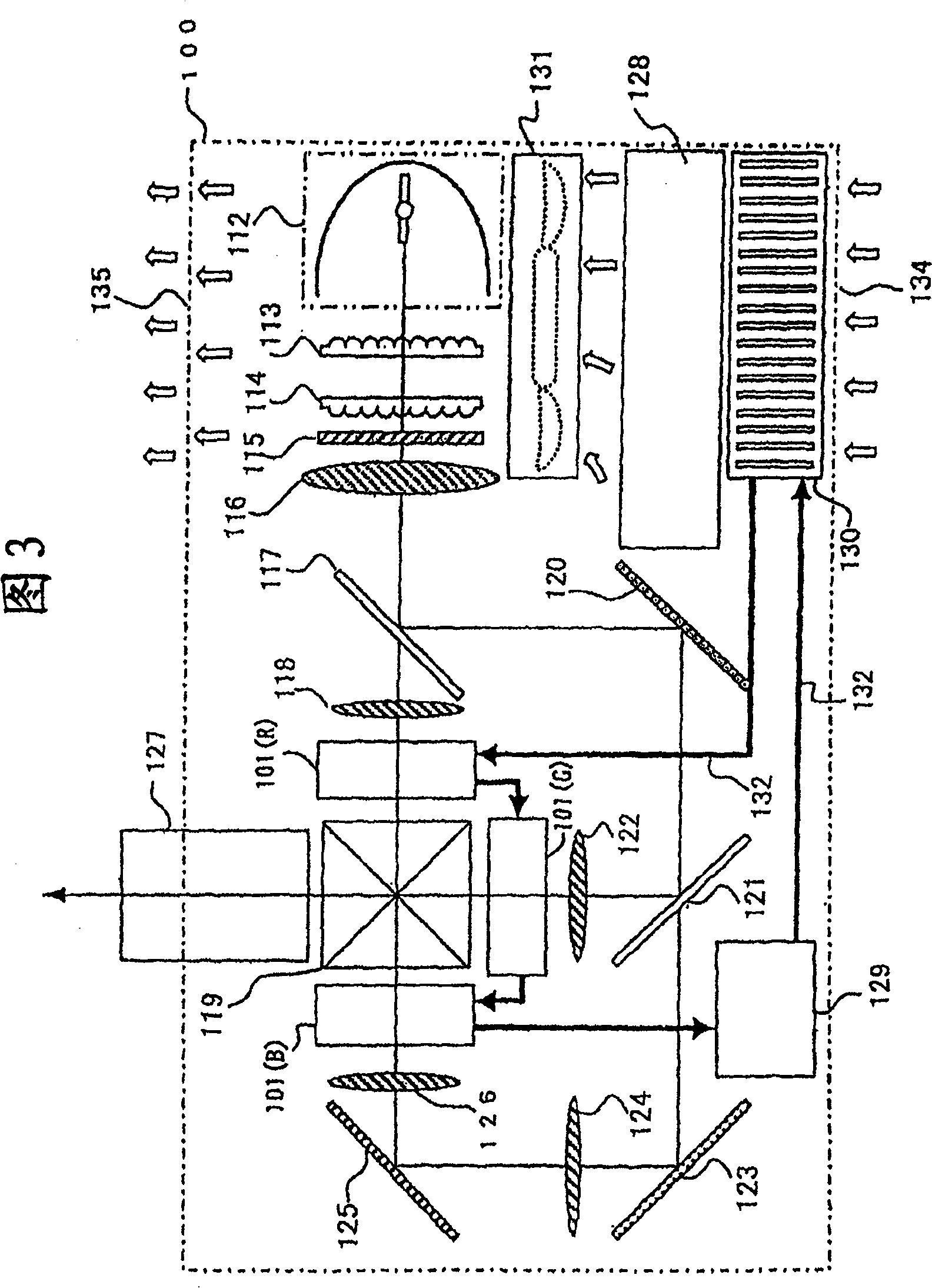
[0047] first, image 3 An example of the overall configuration of a liquid crystal projector including a liquid cooling device for a liquid crystal panel according to an embodiment of the present invention is shown. In the figure, symbol 100 represents the casing of the liquid crystal projector, and as shown in the figure, a light source, such as a metal halide lamp 112 , is arranged inside it. The light emitted by the light source 112 is output as parallel light by the first lens array 113, the second lens array 114, the polarization conversion element 115, and the condenser lens 116 arranged at predetermined positions in the housing. Then the parallel light is introduced into the first dichroic mirror 117, a part of which passes through the first dichroic mirror 117, passes through the first condenser lens 118, and then is introduced into the R (red) liquid crystal panel 101 (R), where the light intensity is modulated, Then it reaches the light-synthesizing prism 119 .

[0...

Embodiment 2

[0071] Embodiment 2 of the present invention will be described below with reference to the drawings. In this second embodiment, the same constituent elements as those of the above-mentioned first embodiment are denoted by the same symbols.

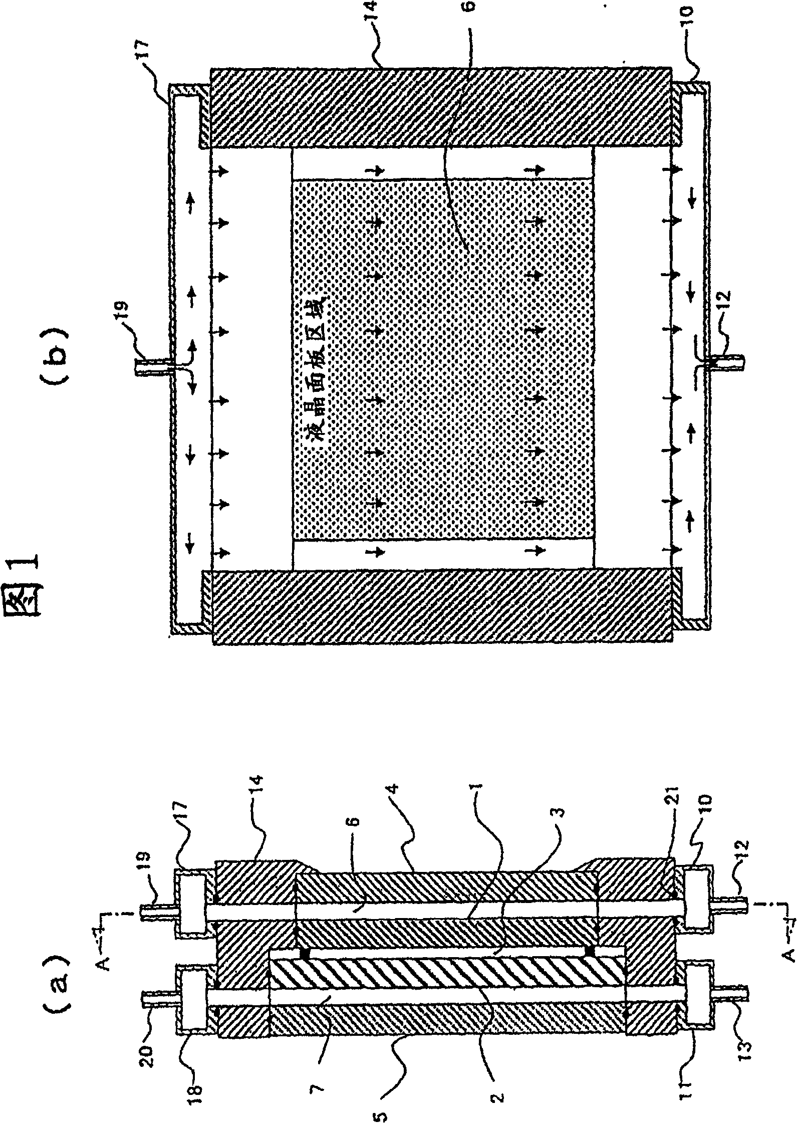
[0072] Figure 8 The detailed internal structure of one liquid crystal panel 101 among the liquid crystal panels 101 (R), 101 (G), and 101 (B) for R, G, and B described above is shown. First, a section showing a cross section of the liquid crystal panel 101 Figure 8 Reference numeral 2 in (a) represents the main structural elements of the liquid crystal panel 101, which is a TFT substrate made of glass, for example, on which a plurality of transistor drive elements are formed on the surface, and an opposing substrate made of glass is provided opposite to the TFT substrate. 1, and then seal the liquid crystal 3 between these transparent substrates 2, 1, thereby forming a liquid crystal panel 101 of one of the three primary colors of R, G...


PUM


Abstract

Provided are a liquid crystal projector, a liquid crystal panel, and a liquid cooling device that are effectively cooled by a liquid cooling cycle and that do not cause image disturbance due to liquid refrigerant passing through the light-transmitting surface of the liquid crystal panel. The light sent by the light source (112) is divided into 3 beams of parallel light, and the 3 beams of light after the division are passed through R, G and B liquid crystal panel (101(R)), panel (101(G)), panel (101( B)) and modulate its intensity, after these modulated light colors are synthesized by the synthesis prism (119), the image is projected by the projection lens (127), and in each liquid crystal panel (101), on the opposite substrate ( 1) A high-resistance flow path for liquid refrigerant is formed between the protective glass plates (4, 5) disposed opposite to the TFT substrate (2), and a buffer portion is formed adjacent to it, or a low-resistance auxiliary flow path is formed surrounding it . In addition, each channel has a uniform and flat thickness "D" channel covering the liquid crystal panel area, and upstream and downstream channel channels with a small thickness "d" and upstream and downstream channels. Buffer runner.

Description

technical field [0001] The present invention relates to a liquid crystal projector in which light emitted from a light source passes through a liquid crystal panel called a light valve and a projection lens, and an image is projected on a screen, and particularly relates to the structure of the liquid crystal panel used in the above-mentioned liquid crystal projector and the liquid refrigerant A liquid cooling device for cooling the above-mentioned liquid crystal panel. Background technique [0002] In recent years, for example, among projection devices (hereinafter simply referred to as "projectors") that enlarge and project color image screens on personal computers, etc., devices that decompose light emitted from light sources such as metal halide lamps into In the three directions, the light intensity of the three primary colors of R, G, or B is modulated by the liquid crystal panel, synthesized by a color synthesis prism, etc., and then projected onto the screen through ...

Claims


Application Information

Patent Timeline
Patent Type & Authority Patents(China)
IPC IPC(8): G03B21/16G02F1/13G03B21/00
Inventor 星野正和南谷林太郎长绳尚寺门秀一
Owner MAXELL HLDG LTD
Why Eureka
Try Eureka