Adjustable resistance with switch

A resistor and variable technology, applied in the direction of sliding contact resistors, etc., can solve the problems that the shape of the key unit 4 becomes larger and cannot be miniaturized, and achieve the effect of reducing the shape, realizing the overall miniaturization, and improving the key performance

Active Publication Date: 2009-08-26
ALPS ALPINE CO LTD
View PDF3 Cites 0 Cited by
  • Summary
  • Abstract
  • Description
  • Claims
  • Application Information

AI Technical Summary

Problems solved by technology

Therefore, the shape of the key unit 4 becomes large, and there is a problem that the overall miniaturization cannot be achieved.

Method used


Image

  • Adjustable resistance with switch
  • Adjustable resistance with switch
  • Adjustable resistance with switch

Examples


Embodiment Construction

[0052] Next, the best mode for implementing the variable resistor with switch of the present invention will be described based on the drawings.

[0053] [Basic configuration of this embodiment]

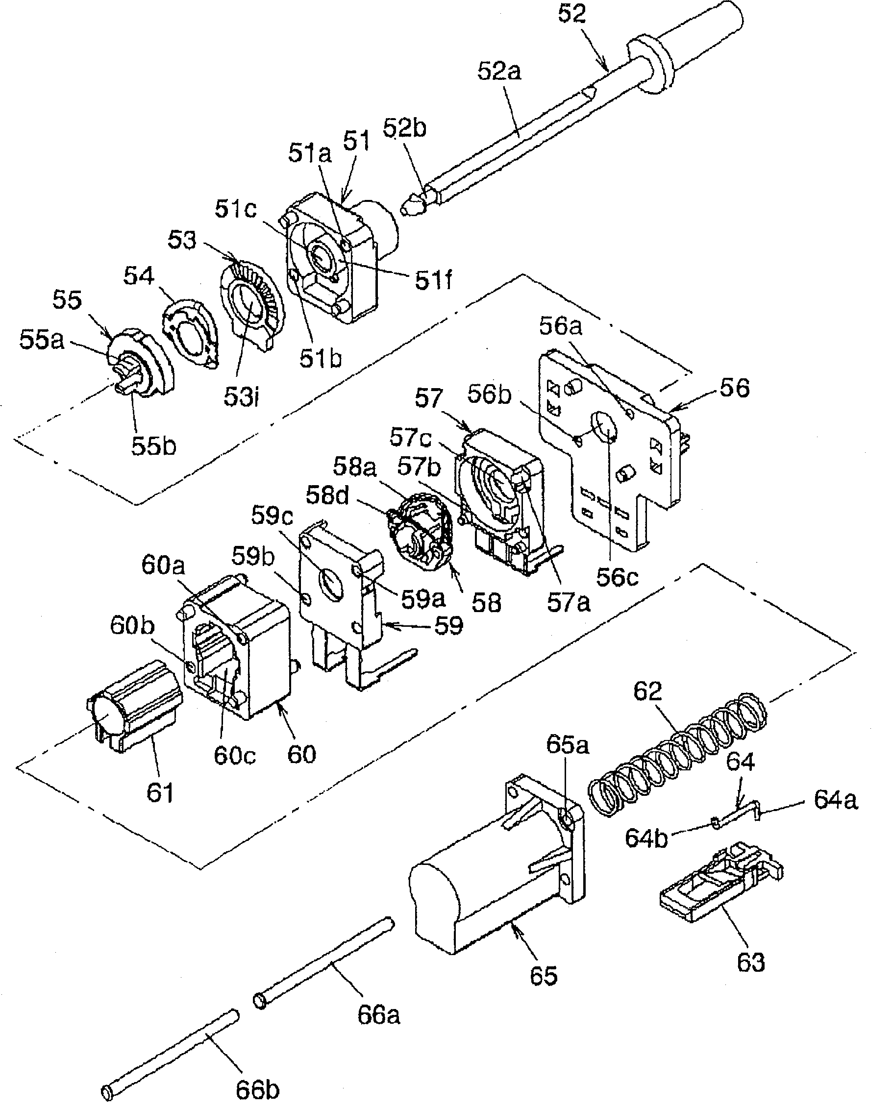
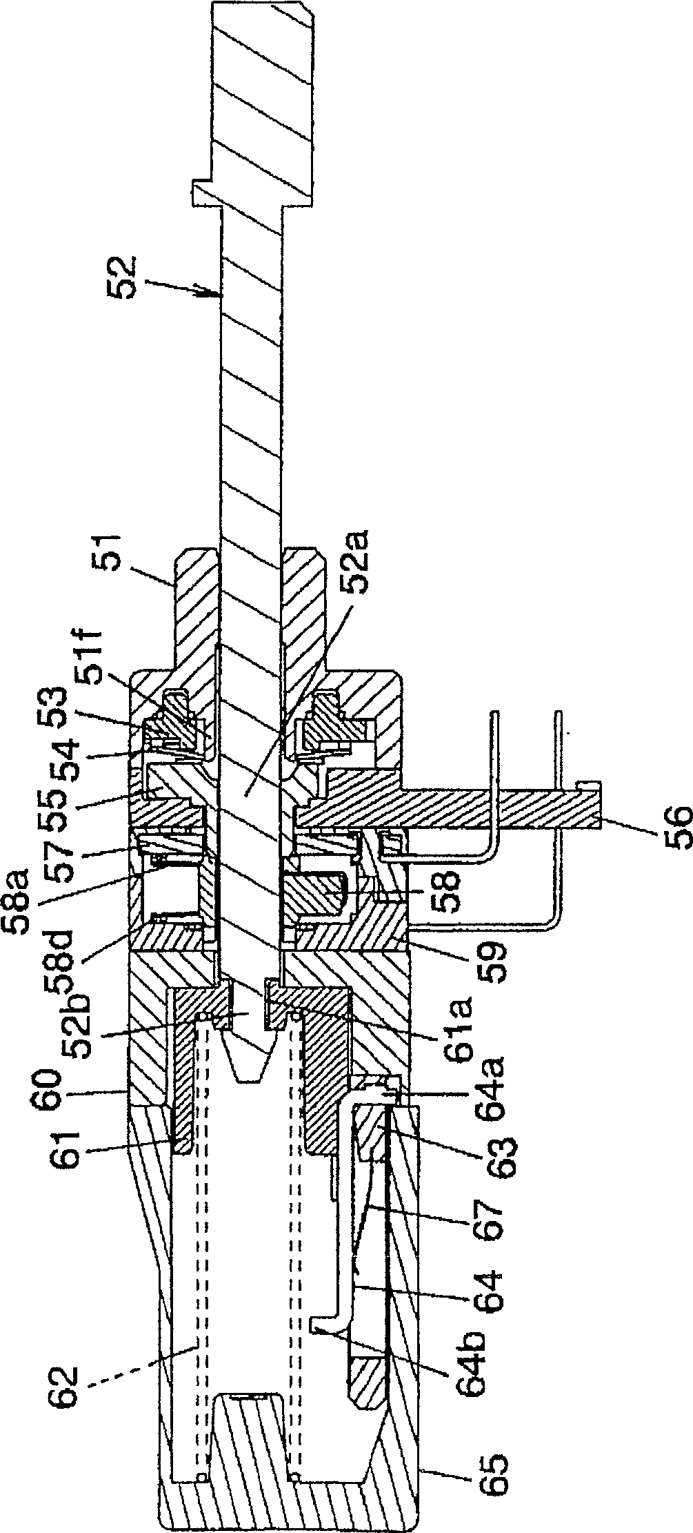
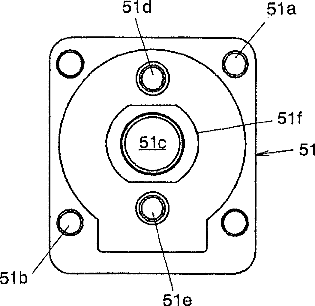
[0054] figure 1 It is an exploded perspective view showing an embodiment of the variable resistor with switch of the present invention; figure 2 It is a side sectional view of this embodiment.

[0055] Such as figure 1 , as shown in 2, in this embodiment, a shaft seat 51 and a rotating shaft 52 are provided, wherein, the shaft seat 51 has, for example, a first mounting hole 51a and a second mounting hole 51b at the corners of the diagonal line and as the The central part has a fixed member forming a circular shaft hole 51c and a sleeve part 51f; the rotating shaft 52 has a non-circular cross-section, that is, an elliptical engaging part 52a, and has a small diameter part near the front end. 52b, and inserted into the shaft hole 51c of the shaft seat 51.

[0056] In addition, a...


PUM


Abstract

A variable resistor with a switch, the key mechanism has a key member (53) and a plate spring (54) for the key, the resistor unit has a resistance substrate (57k) and a first slide key including a contact point (58a1), and a rotary switch There is a second insulating case (59) as a contact substrate and a second slide key including a contact (58d1), and when the rotating shaft (52) is rotated, the contact (58d1) slides on the contact substrate part (59k) to perform When the switch is switched, the second bulging part (54d) of the leaf spring (54) for the key is engaged with the protrusion (53b) of the key member (53) and disengaged, and then the first bulge of the leaf spring (54) for the key is released. The part (54c) engages and disengages from the engaging protrusion (53a) of the key component (53), thereby producing different key tactile sensations. Such a variable resistor with a switch can obtain a key touch feeling that does not produce an uncomfortable feeling and can reduce the shape of the switch part.

Description

technical field [0001] The present invention relates to a variable resistor with a switch, which has a switch unit and a resistor unit, and has a key mechanism that produces a key tactile sensation when a rotating shaft is rotated. Background technique [0002] As a conventional technology of such a variable resistor with a switch, there is a technology described in Patent Document 1, for example. Figure 11-14 It is a figure showing the variable resistor with a switch described in this patent document 1, Figure 11 is a sectional view, Figure 12 yes means Figure 11 Top view of the switching unit on the shown variable resistor with switch, Figure 13 yes means Figure 11 Top view of the keypad on the rheostat with switch shown, Figure 14 yes Figure 11 An explanatory diagram of the operation of the key mechanism provided on the variable resistor with switch shown. [0003] Figure 11-14 The conventional technology shown has a shaft base 1, a rotating shaft rotatably...

Claims


Application Information

Patent Timeline
Patent Type & Authority Patents(China)
IPC IPC(8): H01C10/36
Inventor 沟渕慎一大内利之
Owner ALPS ALPINE CO LTD
Why Eureka
Try Eureka