
Coil with air core of forcipated duplex winding based on printed circuit board

A technology of printed circuit boards and double windings, which is applied to circuits, containing printed electrical components, inductors, etc., can solve the problems of large volume, uncertain direction, and decreased measurement accuracy of air-core coils, and achieve strong resistance to external magnetic field interference , Reduce the occupied space, and the effect of uniform magnetic field strength

Inactive Publication Date: 2009-09-02
武汉格蓝若光电互感器有限公司
View PDF3 Cites 0 Cited by
  • Summary
  • Abstract
  • Description
  • Claims
  • Application Information

AI Technical Summary

Problems solved by technology

[0007] 1. The air-core coil structure in Comparative Document 1 is designed for the shape of the measured current wire to be circular. When the shape of the measured wire is irregular, the distribution of the measured magnetic field changes and is no longer centered on the measured conductor. Uniform circular distribution, after the measured wire passes through the central hole of the air-core coil, the center of the magnetic field generated by the measured current is no longer located in the geometric center of the coil, and the measurement accuracy will decrease
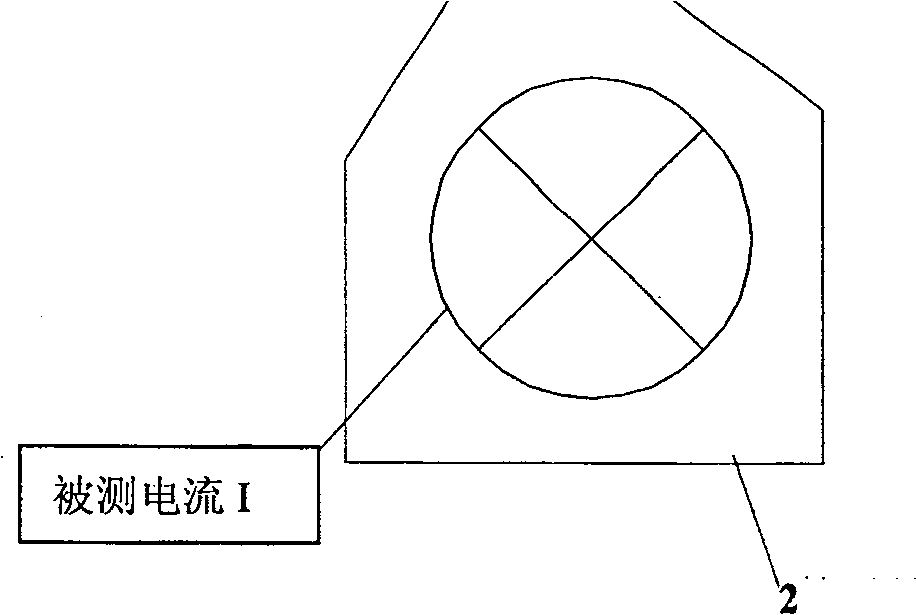
[0008] 2. In the comparison document 1, a whole PCB board is used to form a winding called the No. 1 PCB board, and then the No. 2 PCB board with its mirror image is connected in series to form an air-core coil. If the section of the tested wire is large and the shape Irregularity (for example, in Tokomak for 320kA pulse current measuring device, the diameter of the measured wire is about 1.2 meters, and the edge is irregular hexagonal, the cross-sectional view of the wire is as follows figure 1 As shown), this structure is difficult to realize during design and installation, because the printed circuit board with a diameter of 1.2 meters is difficult to process and the cost is high
At the same time, since the No. 1 PCB board and No. 2 PCB board in Comparative Document 1 are both integral PCBs, the wires to be tested must be disconnected when the formed air-core coils are installed on site.
[0009] 3. When the measured current is small, several air-core coils in the comparison file 1 must be superimposed, and the windings on each PCB are connected in series to improve the sensitivity of the measurement. This will make the air-core coil larger and the application occasions are limited.
[0010] 4. The ability to resist electromagnetic interference needs to be improved
This structure is very different from the model of the ideal air-core coil, which will inevitably affect the ability of the coil to resist external electromagnetic field interference.
And the technical means of Reference 1 only reduces the interference of the external magnetic field perpendicular to the direction of the printed circuit board
In fact, because the external interference magnetic field is complex and the direction is uncertain, it is not enough to only consider reducing the magnetic field interference in the vertical direction. More effective measures must be taken to reduce the influence of the magnetic field parallel to the direction of the PCB board on the measurement.
In addition, due to certain errors in the design and processing of the PCB, it is impossible to achieve absolute uniformity of the winding. When there is interference parallel to the external magnetic field, measurement errors will be directly introduced. This is the technique of the reference document 1 means not considered
[0011] 5. When the external disturbing magnetic field perpendicular to the direction of the printed circuit board passes through the series loop on the connecting board of reference document 1, since there is no return line with the opposite direction of detour, it will destroy the space described in paragraph [0005] of reference document 1. The ideal characteristic of point b of the core coil, which is not mentioned in Reference 1, at this time the external magnetic field will introduce measurement errors
[0012] In short, compared with the air-core coil structure designed by PCB technology in Document 1, the ability to resist electromagnetic interference needs to be improved, and it is not suitable for the situation where the shape of the measured wire is irregular and the measured current is large, and because the coil is composed of a whole PCB, Flexible assembly cannot be achieved, and the tested wire must be disconnected during on-site installation
When the measured current is small, several blocks must be superimposed, and the volume is large

Method used


Image

  • Coil with air core of forcipated duplex winding based on printed circuit board
  • Coil with air core of forcipated duplex winding based on printed circuit board
  • Coil with air core of forcipated duplex winding based on printed circuit board

Examples


Embodiment Construction

[0028] The present invention will be further described in conjunction with the accompanying drawings.

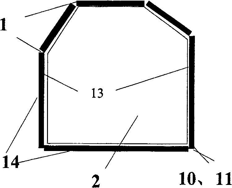
[0029] The air-core coil of the present invention is composed of several printed circuit boards connected end to end. These printed circuit boards have the same thickness and width. The length of each printed circuit board corresponds to a certain side length of the wire shape. The air-core coil of the invention It can realize flexible "fit-to-fit design and installation" without cutting off the tested wire. Each printed circuit board in the coil has two parallel windings, and the two sets of windings are symmetrical along the center line of the circuit board.

[0030] According to specific measurement requirements, the output of the air-core coil can be connected to an integrator or not. Measure the magnitude of the measured current by measuring the output voltage of the coil or the output voltage of the integrator.

[0031] The present invention has no special requirements ...


PUM

PropertyMeasurementUnit
diameteraaaaaaaaaa
thicknessaaaaaaaaaa
thicknessaaaaaaaaaa

Abstract

The invention relates to a clamp-type double-winding air-core coil based on a printed circuit board. The air-core coil is composed of several PCBs connected in series head to tail. The length of each PCB is designed according to the shape of the wire to be tested, and each PCB has same thickness and width. Each PCB has two groups of conductive wiring parallel to each other and symmetrically distributed along the middle line and bottom of each PCB, forming two symmetrical upper and lower windings respectively, and the conductive loop wiring directions of the upper and lower windings are opposite. The symmetrical distribution of the windings can effectively reduce the interference of the external electromagnetic field. The shape of the air-core coil of this structure can be changed flexibly, the volume is small, and the tested wire does not need to be disconnected during installation. It is very suitable for applications where the measured wire has an irregular shape. Compared with the existing air-core coil structure, the magnetic field in the coil is more uniform, the windings are denser, the measurement accuracy is higher, and the ability to resist external electromagnetic field interference is stronger.

Description

technical field [0001] The present invention relates to an air-core coil for measuring magnetic field or current, also known as Rogowski coil, specifically, it is a clamp-type double-winding air-core coil manufactured by using a printed circuit board (Print Circuit Board, hereinafter referred to as PCB). Background technique [0002] Air core coils were originally used to measure magnetic fields. Early air-core coils could not be used for current measurement because the output voltage and power of the coil were not sufficient to drive subsequent measuring equipment. With the development of microprocessor-based relay protection and measurement technology, air-core coils are very suitable for measuring current in these occasions. [0003] The measurement accuracy of the air-core current sensor depends on a stable mutual inductance constant M. Therefore, in order to obtain high-precision air-core coils, the following principles must be followed during production: constant coi...

Claims


Application Information

Patent Timeline
Patent Type & Authority Patents(China)
IPC IPC(8): H01F38/28H05K1/16
Inventor 李红斌
Owner 武汉格蓝若光电互感器有限公司
Learn More