
Method for laying structures of forming underground tunnel and its structure

A laying method and technology for underground tunnels, applied in tunnels, tunnel linings, underground chambers, etc., can solve problems such as difficult construction, uneconomical construction, and slow construction progress

Inactive Publication Date: 2009-09-09
NTS ENC
View PDF4 Cites 0 Cited by
  • Summary
  • Abstract
  • Description
  • Claims
  • Application Information

AI Technical Summary

Problems solved by technology

[0004] First, because the tunnel excavation is carried out first, and then the erection process is carried out, the erection process needs to be carried out many times, which is very cumbersome and has certain safety hazards
[0005] Second, in order to carry out the erection process, a plurality of scaffolds 1 will be connected with a plurality of screws to be laid after tunnel excavation, which not only increases the difficulty of work, but also requires a lot of manpower, long construction period and uneconomical. construction progress is slow
[0006] Third, when excavating, if the excavation is too deep, when the foundation is weak, needless to say, the excavation process has a high risk of foundation or rock plate collapse or subsidence during the erection process after the excavation work. security incident
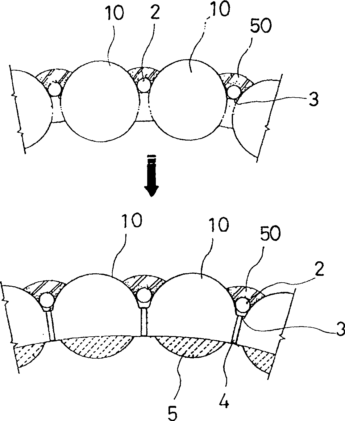
[0010] First, all the very long small-diameter pipelines 2 must be forcibly pressed into the steel pipes 10 for laying. When the length is relatively long, since there is no pipeline transmission pipe and adjustment device, it is difficult to control the directionality, and there are defects in the linear progress. , so it is difficult to lay
When the gaps between the steel pipes 10 are large, the small-diameter pipes 2 cannot prevent landslides, and a lot of equipment and construction costs will be consumed
When there are stones or the soil layer moves up, the direction changes, which makes the linear progress uncertain. When there are huge stones, the construction will be very difficult. When the filling work is carried out inside the steel pipe at the same time, the steel pipe will be corroded and become deformed. Fragile, difficult to prevent groundwater and soil loss, very uneconomical when filling the interior of pipes
[0011] Second, when the curved surface parts of the side of the above-mentioned steel pipe 10 opposite to a certain distance are cut to form mutually open cut parts, there is a danger of collapse due to the pressure of the upper soil layer.
After the upper and lower ends of the incision are welded with iron plates 3, it is necessary to lay struts 4. At this time, the pressure of the soil layer will be transmitted to the lower iron plates, so it is necessary to lay protective steel plates separately, which makes the work complicated and requires other Iron plate equipment consumes too much equipment cost and is uneconomical
Moreover, the ability to withstand external stress is weak. If there are no necessary measures in advance, it will be structurally unsafe.
[0012] The 3rd, fill above-mentioned steel pipe interior 10 bottoms with polystyrene foam plastics 5 as the work of casting mould, need expend a lot of equipment cost, when construction material is in short supply, be difficult to buy polystyrene foam plastics 5, need to process or special for steel pipe 10 Customized Styrofoam 5, if the size of steel pipe 10 changes, you need to re-purchase Styrofoam 5 that meets the size, which is very inconvenient
In addition, after the completion of the project, the waste of polystyrene foam 5 will pollute the environment, and it is also very difficult to deal with it.
[0013] Fourth, since the inside of the steel pipe is filled with concrete without reinforcement, the ability to withstand external stress is weak, it is difficult to explain the structure, and it is necessary to add a protective steel plate, which requires a lot of extra costs, which is not only uneconomical, but also reduces the safety index

Method used


Image

  • Method for laying structures of forming underground tunnel and its structure
  • Method for laying structures of forming underground tunnel and its structure
  • Method for laying structures of forming underground tunnel and its structure

Examples


Embodiment approach 1

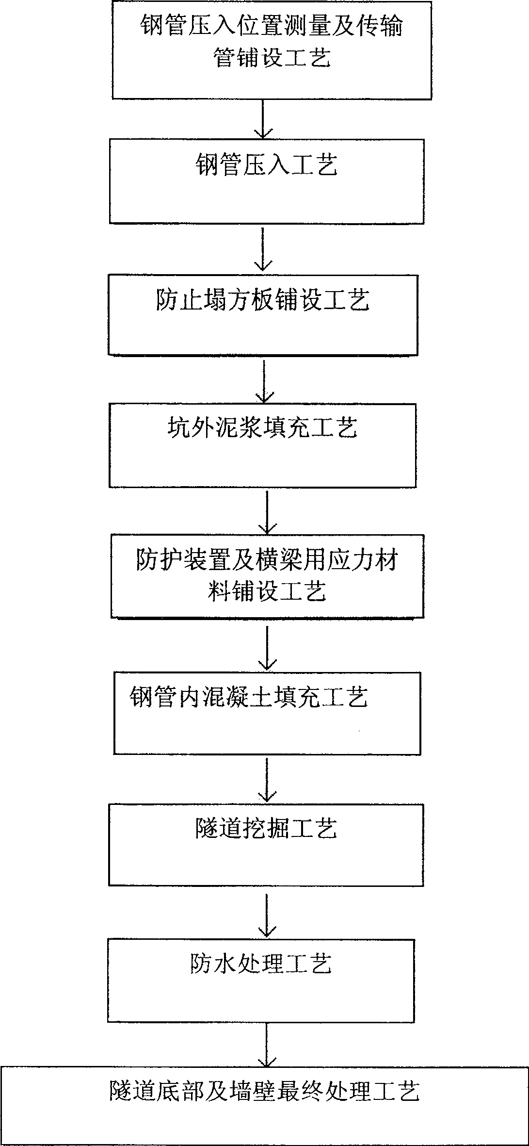
[0062] refer to image 3 process diagrams involved, with Figure 4 , Figure 5a , Figure 5b based on Figure 6a , Figure 6b , the first embodiment of the present invention will be described in detail.

[0063] Steel pipe pressing position measurement and transmission pipe laying process A:

[0064] Before pressing into the steel pipe 10, accurate measurement is carried out at the appropriate position according to the scheduled tunnel construction, and the input port 21 of the anti-collapse plate is formed at the front end of the steel pipe 10, combined with the transmission pipe 20 with the pressing-in direction adjustment device 30, the pressing-in of the steel pipe is completed 10 preparations.

[0065] Steel pipe pressing process B:

[0066] Place the steel pipe 10 at the exact propulsion position, press it in step by step with the hydraulic jack and the propulsion auxiliary pipe, and measure the position every 1M, and use the press-in direction adjustment device 3...

Embodiment approach 2

[0082] refer to image 3 process diagrams involved, with Figure 4 , Figure 5a , Figure 5b based on Figure 7a , Figure 7b , the second embodiment of the present invention will be described in detail.

[0083] The second embodiment of the present invention uses the same method as the above-mentioned first embodiment, and sequentially performs steel pipe pressing position measurement, transmission pipe laying process A, steel pipe pressing process B, collapse prevention plate laying process C, and mud filling outside the pit After process D, process E of laying stress materials for protective devices and beams, process F of concrete filling in steel pipes, and process G of tunnel excavation:

[0084] Waterproof treatment process H:

[0085] A waterproof iron plate 120 is used to connect the steel pipe 10 on one side protruding from the tunnel portion 500 and the steel pipe 10 on the other side to prevent water from penetrating into the tunnel and to play a waterproof r...

Embodiment approach 3

[0089] refer to image 3 engineering drawings involved, with Figure 4 , Figure 5a , Figure 5b based on Figure 8a , Figure 8b , the third embodiment of the present invention will be described in detail.

[0090] The third embodiment according to the present invention uses the same method as the above-mentioned first embodiment, and sequentially performs steel pipe pressing position measurement, transmission pipe laying process A, steel pipe pressing process B, collapse prevention plate laying process C, and mud filling outside the pit After process D, process E of laying stress materials for protective devices and beams, process F of concrete filling in steel pipes, and process G of tunnel excavation:

[0091] Waterproof treatment process H:

[0092] Asphalt or a thin waterproof material layer 121 is formed on the entire wall of the tunnel portion 500 including the outer layer of the steel pipe 10 protruding toward the tunnel portion 500 for waterproofing.

[0093] ...


PUM


Abstract

The invention relates to a structure laying method and structure for forming an underground tunnel. Different from the past, the present invention does not press into long-distance small-diameter pipelines that cannot be erected between steel pipes and is uneconomical, and lays wooden anti-slump plates through the input port of the anti-slip plate on the transmission pipe, so that the construction is simple and the cost of materials is low. , At the same time, due to the laying through the transmission pipe, boulders and other obstacles can be quickly removed, making the laying easier and has good straightness.

Description

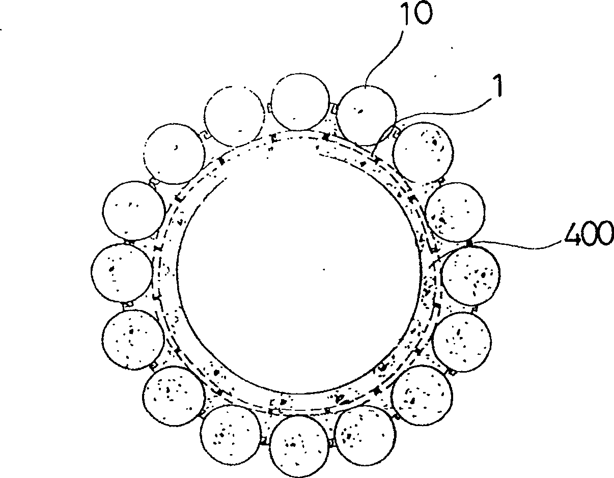
【Technical field】 [0001] The present invention relates to a structure laying method and structure for forming an underground tunnel. It is possible to improve the method of laying the structure that forms the tunnel in the middle, make it able to fully withstand the stress in advance, and then excavate the inside of the structure to form an underground tunnel, so that the construction of a strong and waterproof tunnel structure can be completed in a short period of time. 【Background technique】 [0002] Generally, in order to form a tunnel, it is necessary to lay a tunnel structure capable of withstanding stress generated from the outside of the tunnel, and the conventional method of laying a tunnel structure will be described below. [0003] First, if figure 1 As shown, large-diameter steel pipes 10 of the same shape as the tunnel are pressed into the ground at a certain interval, the inside of the steel pipe 10 and the outside of the steel pipe 10 are poured, and then the ...

Claims


Application Information

Patent Timeline
Patent Type & Authority Patents(China)
IPC IPC(8): E21D9/00E21D11/10E21D11/38
Inventor 金正允
Owner NTS ENC
Learn More