Method for laying structures of forming underground tunnel and its structure
A laying method and technology for underground tunnels, applied in tunnels, tunnel linings, underground chambers, etc., can solve the problems of cumbersome, long construction period, and uneconomical filling of the interior of the pipeline.
- Summary
- Abstract
- Description
- Claims
- Application Information
AI Technical Summary
Problems solved by technology
Method used
Image
Examples
Embodiment approach 1
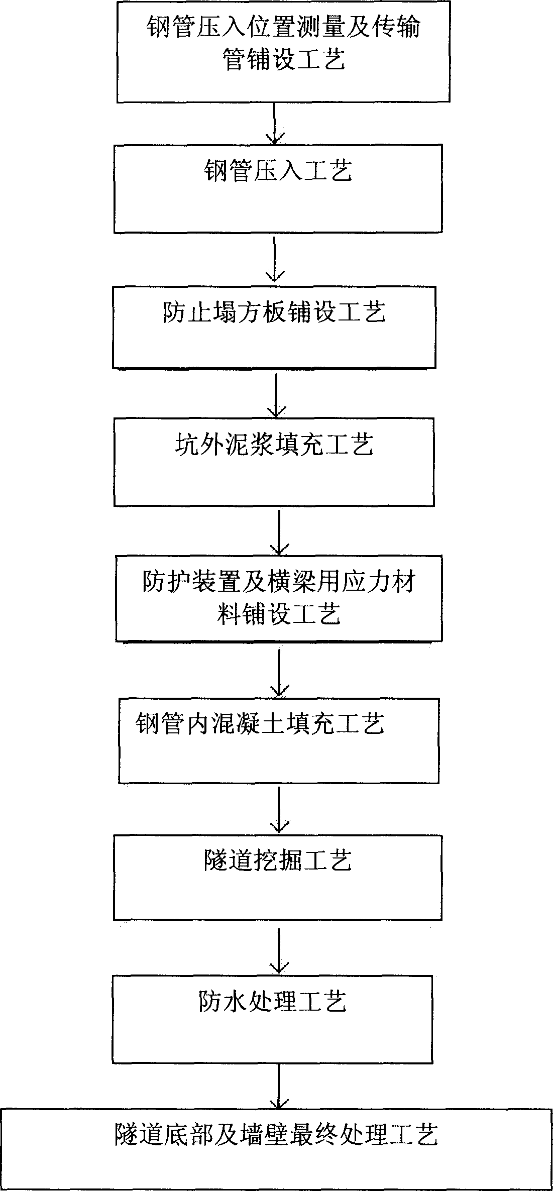
[0062] refer to image 3 Process diagrams involved, to Figure 4 , Figure 5a , Figure 5b based on Figure 6a , Figure 6b , the first embodiment of the present invention will be described in detail.
[0063] Steel pipe pressing position measurement and transmission pipe laying process A:
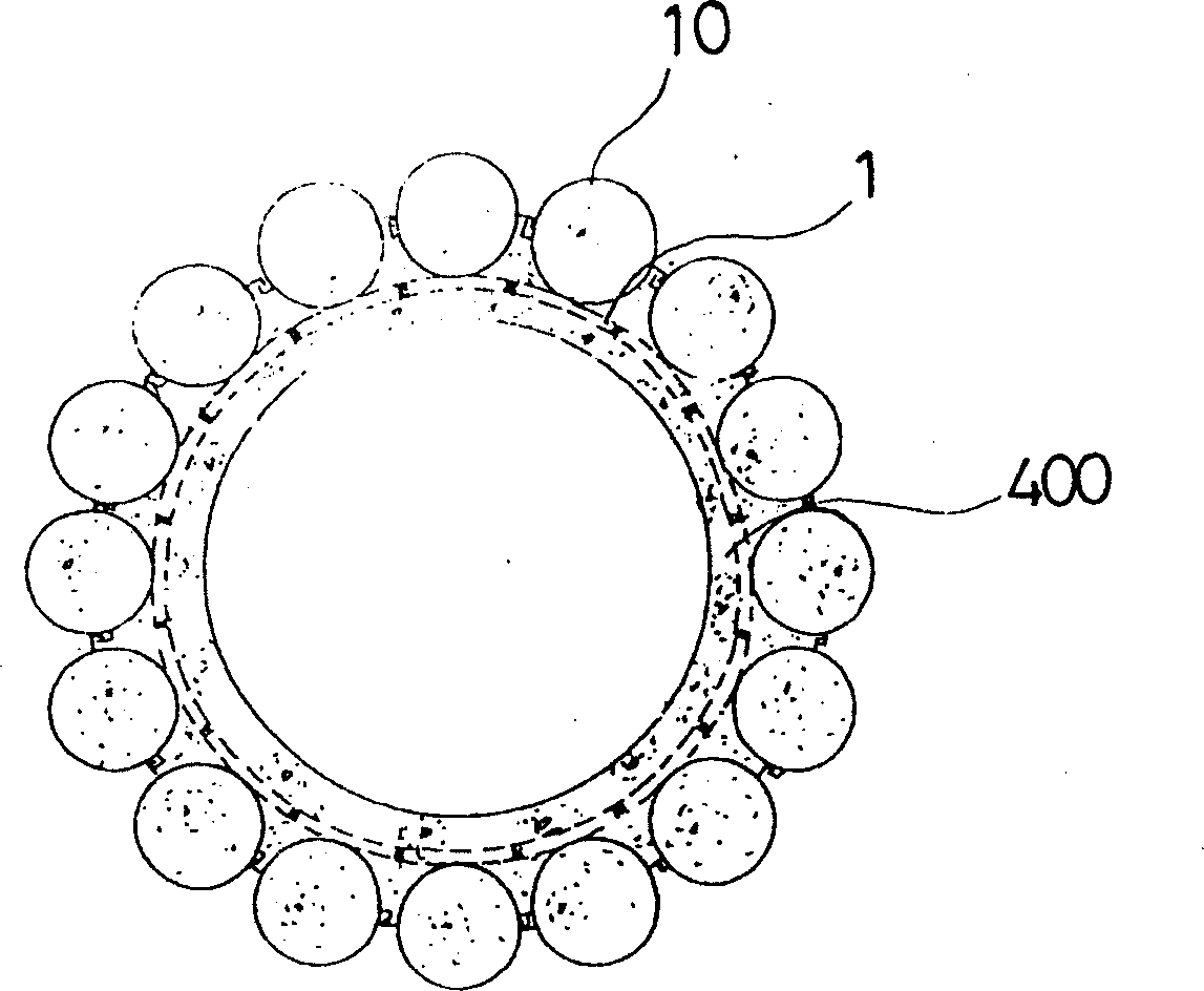
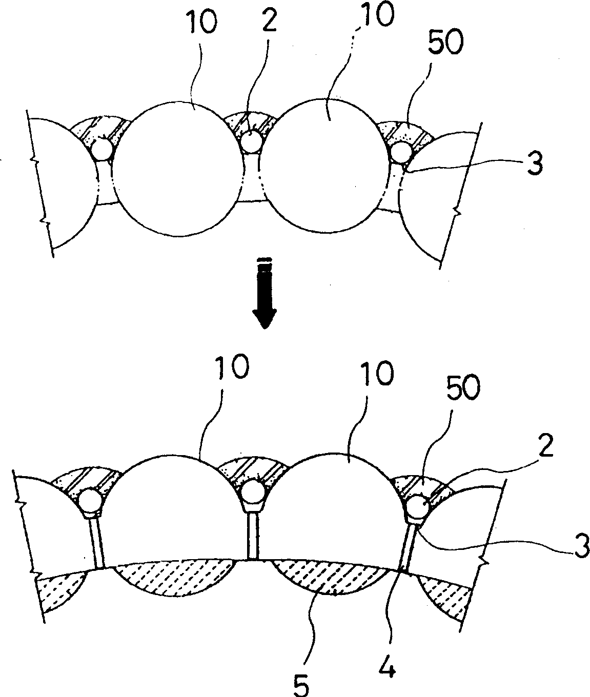
[0064] Before the steel pipe 10 is pressed in, an accurate measurement is made at the appropriate position according to the planned tunnel construction face, and the input port 21 for preventing the collapse plate is formed at the front end of the steel pipe 10. Combined with the transmission pipe 20 with the press-in direction adjustment device 30, the steel pipe is pressed into the steel pipe. 10 preparations.
[0065] Steel pipe press-in process B:
[0066] The steel pipe 10 is placed at the exact propulsion position, and the hydraulic jack and propulsion auxiliary pipe are used to press in step by step, and the position measurement is carried out every 1M, and the press-in direc...
Embodiment approach 2
[0082] refer to image 3 Process diagrams involved, to Figure 4 , Figure 5a , Figure 5b based on Figure 7a , Figure 7b , the second embodiment of the present invention will be described in detail.
[0083] The second embodiment of the present invention uses the same method as the above-mentioned first embodiment to perform the steel pipe press-in position measurement and the transfer pipe laying step A, the steel pipe press-in step B, the collapse prevention plate laying step C, and the mud filling outside the pit in this order. Process D, the laying process E of the stress material for guards and beams, the filling process F of the concrete in the steel pipe, and the tunnel excavation process G are carried out after:
[0084] Waterproof treatment process H:
[0085] The steel pipe 10 on one side and the steel pipe 10 on the other side protruding toward the tunnel portion 500 are connected by a waterproof iron plate 120 to prevent water from infiltrating into the tu...
Embodiment approach 3
[0089] refer to image 3 involving engineering drawings to Figure 4 , Figure 5a , Figure 5b based on Figure 8a , Figure 8b , the third embodiment of the present invention will be described in detail.
[0090] The third embodiment according to the present invention uses the same method as the above-mentioned first embodiment to perform the steel pipe press-in position measurement and the transfer pipe laying step A, the steel pipe press-in step B, the slump prevention plate laying step C, and the mud filling outside the pit in this order. Process D, the laying process E of the stress material for guards and beams, the filling process F of the concrete in the steel pipe, and the tunnel excavation process G are carried out after:
[0091] Waterproof treatment process H:
[0092] Asphalt or a thin waterproof material layer 121 is formed on the entire wall of the tunnel portion 500 including the outer layer of the steel pipe 10 on one side protruding toward the tunnel po...
PUM
 Abstract
Description
Claims
Application Information
 - R&D
- Intellectual Property
- Life Sciences
- Materials
- Tech Scout
- Unparalleled Data Quality
- Higher Quality Content
- 60% Fewer Hallucinations
Browse by: Latest US Patents, China's latest patents, Technical Efficacy Thesaurus, Application Domain, Technology Topic, Popular Technical Reports.
© 2025 PatSnap. All rights reserved.Legal|Privacy policy|Modern Slavery Act Transparency Statement|Sitemap|About US| Contact US: help@patsnap.com


