
Elevator

An elevator and rope technology, which is applied in the elevator field, can solve the problems of instability, high cost, and the inability to provide man-made fiber ropes, and achieves the effect of reducing installation time and lateral support force.

Inactive Publication Date: 2009-09-16
KONE CORP
View PDF6 Cites 0 Cited by
  • Summary
  • Abstract
  • Description
  • Claims
  • Application Information

AI Technical Summary

Problems solved by technology

Such a solution is unstable and the ropes thus obtained are lighter than steel wire ropes, but at least in the case of elevators designed for the most common lifting heights, man-made fiber ropes do not offer any significant advantages, especially since they are used in conjunction with Very expensive compared to steel wire rope

Method used


Image

  • Elevator
  • Elevator
  • Elevator

Examples


Embodiment Construction

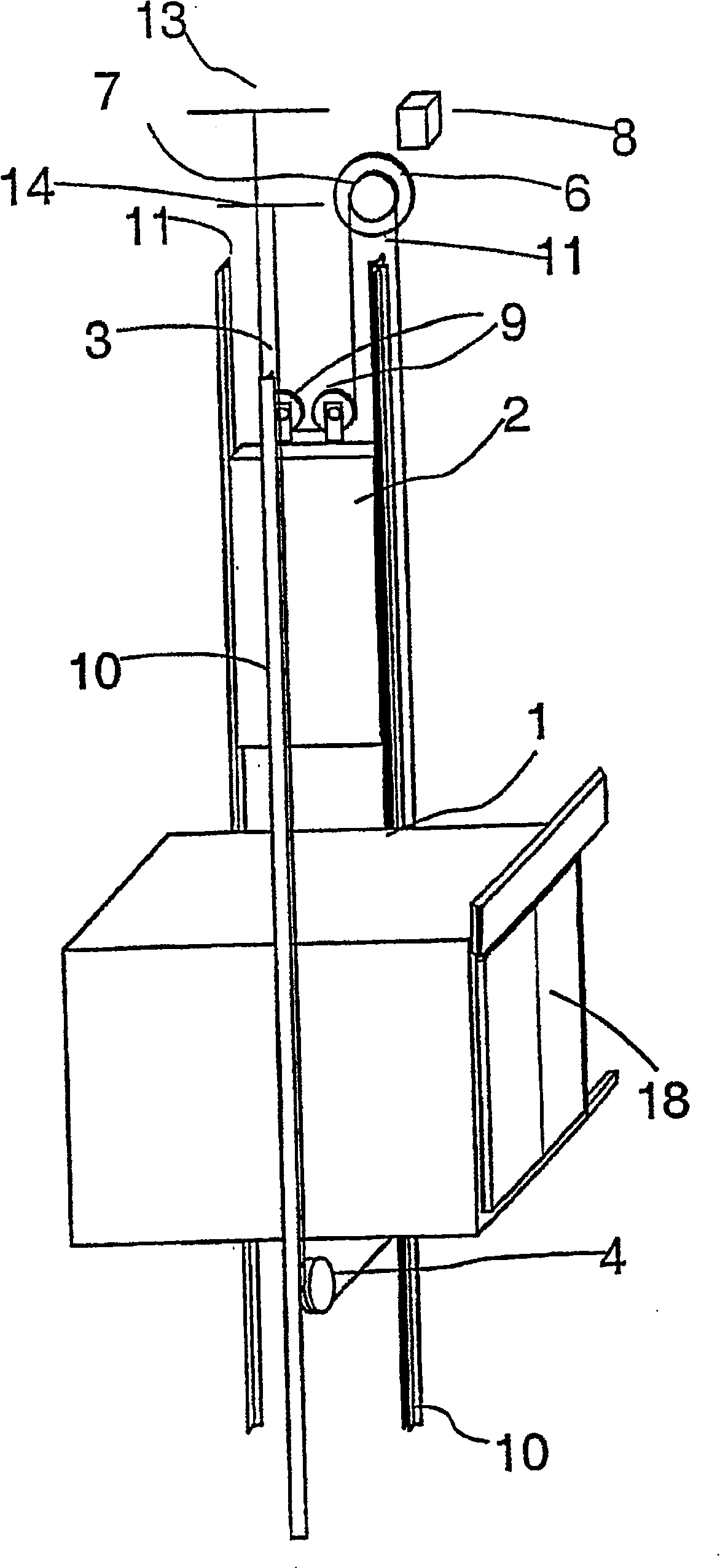
[0069] figure 1 It is a schematic diagram of the structure of an elevator. This elevator is preferably a machine-room-less elevator in which the drive machine 6 is placed in the elevator shaft. The elevator shown in the figure is a traction sheave elevator with the machine above. The running of the elevator hoisting rope 3 is as follows: one end of the rope is immovably fixed to an anchorage 13 arranged in the upper part of the shaft above the path of the counterweight 2 moving along the counterweight guide rails 11 . From this anchorage, the rope goes down and around the deflection pulleys 9 on which the counterweight is suspended, these deflection pulleys 9 are rotatably mounted on the counterweight 2, and the rope 3 then goes up to the traction sheave 7 of the driving machine 6 , bypass the traction sheave along each rope groove on the sheave. From the traction sheave 7, the rope 3 goes down to the elevator car 1 moving along the car guide rails 10, passes under the car ...


PUM


Abstract

In an elevator, preferably one without machine room, a hoisting machine (6) engages a set of hoisting ropes (3) via a traction sheave, said set of hoisting ropes having a load-bearing part twisted from steel wires of circular and / or non-circular crosssection, and in which elevator there is diverting pulleys (9, 4) of which some is made larger than traction sheave. The weight of the hoisting machine of the elevator is at most about 1 / 5 of the weight of the nominal load of the elevator.

Description

technical field [0001] The present invention relates to an elevator. Background technique [0002] One of the goals of elevator research and development work is to achieve efficient and economical use of building space. In recent years, this research and development work has, among other things, resulted in a variety of machine room-less elevator solutions. Some good examples of machine room-less elevators are disclosed in specifications EP 0631967 (A1) and EP 0631968. The various elevators described in these technical specifications are quite efficient in terms of space utilization, since they already make it possible to dispense in buildings with the space required for the elevator machine room without enlarging the elevator shaft. In the various elevators disclosed in these specifications, the machine is compact in at least one direction, but in other directions it may have much larger dimensions than conventional elevator machines. [0003] In these basically good ele...

Claims


Application Information

Patent Timeline
Patent Type & Authority Patents(China)
IPC IPC(8): B66B11/00B66B7/06B66B11/08
CPCB66B11/009B66B7/06
Inventor 埃斯科·奥兰科乔马·穆斯塔拉蒂佩卡·兰塔南西莫·梅基马蒂拉
Owner KONE CORP
Learn More