System restarting circuit and its system restarting method

A technology of system restart and system power supply, applied in the direction of data reset device, etc., can solve the problems of increased production cost, failure to provide, easy to damage internal circuits, etc., and achieve the effect of simple structure

Inactive Publication Date: 2009-09-23
RRT TECH LTD
View PDF5 Cites 0 Cited by
  • Summary
  • Abstract
  • Description
  • Claims
  • Application Information

AI Technical Summary

Problems solved by technology

And to start the system again, the user must press a power on / off switch (not shown) so that terminal A inputs a start signal PW ON / OFF to start the bipolar junction transistor 14, so that the field effect transistor 16 can establish a channel to start the system power supply circuit 18 by turning on the current again. Therefore, the known circuit structure cannot automatically complete the entire restart operation through a reset button
[0003] Generally speaking, the system restart mechanism can be divided into two types: hardware restart and software restart. Since portable electronic products are light, thin and small, they generally cannot provide hardware restart function, so the restart is usually performed by software. For example, Taiwan Patent Application No. No. 094101935 discloses that it pre-sets a specific command in the handheld device, and activates the command through the operation interface to restart when it needs to be reset. However, when the software or the microprocessor cannot work, the command cannot operate , the user can only power off the electronic product, such as unplugging the battery, to force shutdown and restart, which is not only time-consuming, but also more likely to damage the internal circuit, which is inconvenient for the user
[0004] Or as disclosed in Taiwan Patent Application No. 087204117 "power reset circuit device for notebook computer", its circuit structure is as follows figure 2 As shown, when the reset switch 20 is touched, it will cause the input voltage of the peripheral device control unit 22 to change, thereby triggering the peripheral device control unit 22 to send a power-on signal to the power supply unit 24 to restart the power supply unit. In the case of restarting, restarting can be carried out through the power reset circuit device without turning off the power of the notebook computer, but the structure of this device is complicated, requiring units such as field effect transistor (FET) 26 and pulse width modulation 28, Increase the production cost of the product

Method used


Image

  • System restarting circuit and its system restarting method
  • System restarting circuit and its system restarting method
  • System restarting circuit and its system restarting method

Examples


Embodiment Construction

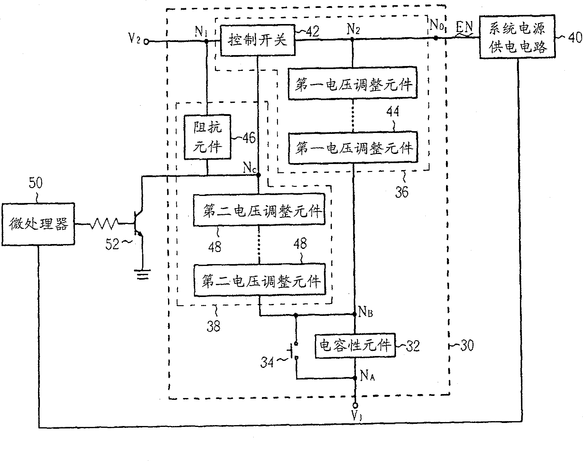
[0027] see image 3 , image 3 It is a block diagram of an embodiment of the system restart circuit of the present invention. In this embodiment, the system reset circuit 30 includes a capacitive element 32 (for example, a capacitor), the first terminal NA of which is coupled to the first voltage level V1; a restart switch 34, coupled to the end of the capacitive element 32 The second terminal NB and the first voltage level V1 are used to selectively couple the second terminal NB of the capacitive element 32 to the first voltage level V1; the first circuit 36 ​​is coupled to the second voltage level V2 , the second terminal NB of the capacitive element 32 and the system power supply circuit 40 ; and the second circuit 38 are coupled to the first circuit 36 ​​. Please note that without affecting the technical disclosure of the present invention, image 3 Only those circuit elements related to the system reset circuit 30 of the present invention are shown.

[0028] The first...


PUM


Abstract

The invention provides a system restart circuit and a system restart method thereof. The reset circuit includes a capacitive element, the first end of which is coupled to the first voltage level; a reset switch is used to selectively couple the second end of the capacitive element to the first voltage level; the first circuit, It is used to establish a current path between the second voltage level and the capacitive element within the restart time, and set the voltage level of the start signal of the system power supply circuit at its output end according to the voltage level of the second end of the capacitive element. level; and the second circuit is used to control the first circuit to continuously establish the current path during the restart time. In this way, the present invention will automatically restart the system when a restart signal is detected, and the purpose of hardware restart can be achieved at a relatively low cost.

Description

technical field [0001] The invention provides a system restart circuit and a restart method, in particular to a spontaneous system restart circuit and a system restart method suitable for portable electronic products. Background technique [0002] figure 1 It is a schematic diagram of a power processing circuit of a known portable electronic product such as a notebook computer, a portable audio-video player, a mobile phone, and a handheld game device. The junction transistor (BJT) 14 is turned off, so that the source-gate voltage (VSG) of the field effect transistor (FET) 16 is lower than its turn-on voltage and cut off. At this time, the current provided by the power supply VBAT cannot be introduced into the system power supply circuit 18, so the overall system stops functioning. And to start the system again, the user must press a power on / off switch (not shown) so that terminal A inputs a start signal PW ON / OFF to start the bipolar junction transistor 14, so that the fi...

Claims


Application Information

Patent Timeline
Patent Type & Authority Patents(China)
IPC IPC(8): G06F1/24
Inventor 林轩羽叶洧豪
Owner RRT TECH LTD
Why Eureka
Try Eureka