Ultrasonic transducer

A technology of ultrasonic energy conversion and piezoelectric ceramic sheet, which is applied in measuring devices, using sound waves/ultrasonic waves/infrasonic waves to analyze solids, and using sound waves/ultrasonic waves/infrasonic waves to analyze materials, etc. and other problems, to achieve the effect of easy replacement

Inactive Publication Date: 2016-10-12
HUAZHONG UNIV OF SCI & TECH
View PDF14 Cites 0 Cited by
  • Summary
  • Abstract
  • Description
  • Claims
  • Application Information

AI Technical Summary

Problems solved by technology

Atomic force microscopy is imaging through the interaction between atoms, but it can only image the surface and cannot detect the interior
Ultrasonic imaging can image the interior of the sample, but it also has problems. In previous experiments, due to the very small size of the probe cantilever, it is very difficult to realize the combination of the probe and the cantilever. Realized, but considering that the probe is a consumable item in the actual experiment and needs to be replaced frequently, so this method of plating the piezoelectric material directly on the tiny cantilever, or plating the piezoelectric material on the tiny base of the fixed cantilever Extremely costly; if the piezoelectric material is plated on the tiny base that holds the probe and then fixed to the external fixture, it will affect the vibration, which will further affect the generation of ultrasound, and finally affect the loading of the signal
[0003] In addition, an external circuit is required to drive the piezoelectric material. After the piezoelectric material is directly plated on it, the lead electrode needs to be connected to the external drive circuit. The tiny structure of the probe has a great impact on the work of the lead electrode later, making it very difficult.
[0004] In addition, in the existing technology, a piezoelectric material is usually added under the cantilever, and the tiny piezoelectric sheet on the cantilever is electrically driven to vibrate to generate ultrasound, which has a low frequency

Method used


Image

  • Ultrasonic transducer
  • Ultrasonic transducer
  • Ultrasonic transducer

Examples


Embodiment Construction

[0024] In order to make the object, technical solution and advantages of the present invention clearer, the present invention will be further described in detail below in conjunction with the accompanying drawings and embodiments. It should be understood that the specific embodiments described here are only used to explain the present invention, not to limit the present invention. In addition, the technical features involved in the various embodiments of the present invention described below can be combined with each other as long as they do not constitute a conflict with each other.

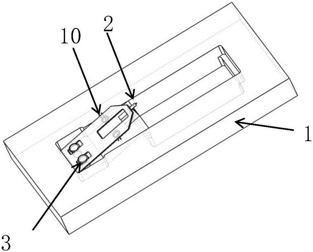
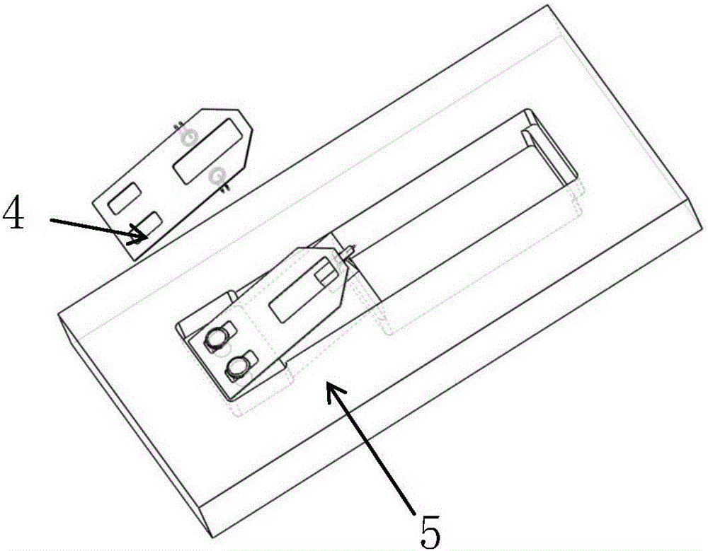
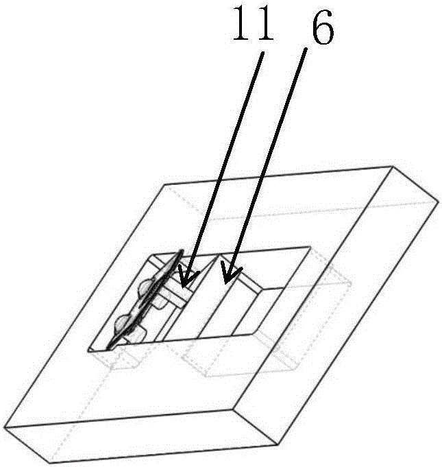
[0025] refer to Figure 1 to Figure 5 , an ultrasonic transducer, comprising a base 1, a lower piezoelectric ceramic sheet 6, a pad 11, a stainless steel shrapnel support 10, a fixed sheet 8, a cantilever 2, a probe 9 and an upper piezoelectric ceramic sheet 7, wherein,

[0026] The upper surface of the base 1 is provided with a groove, and the lower piezoelectric ceramic sheet 6 is installed a...


PUM


Abstract

The invention belongs to the field of ultrasonic imaging equipment, and discloses an ultrasonic transducer. The ultrasonic transducer comprises a base, a lower piezoelectric ceramic piece, a cushion block, a stainless steel elastic sheet support, a cantilever, a probe and upper piezoelectric ceramic pieces. A groove is formed in the upper surface of the base, and the lower piezoelectric ceramic piece is installed in the groove of the base and is connected with the cushion block; the stainless steel elastic sheet support is connected with the base through the cushion block, the stainless steel elastic sheet support and the cushion block cooperate to clamp one end of the cantilever, and the probe is fixedly installed at the other end of the cantilever; the two upper piezoelectric ceramic pieces are installed on the upper surface of the end, close to the cushion block, of the stainless steel elastic sheet support, and each upper piezoelectric ceramic piece is installed on the stainless steel elastic sheet support through a turnup electrode. The ultrasonic transducer and the cantilever are integrated in a split mode, the probe can be replaced conveniently, and high-frequency composite ultrasonic waves can be generated.

Description

technical field [0001] The invention belongs to the field of ultrasonic imaging equipment, and more specifically relates to an ultrasonic transducer. Background technique [0002] Ultrasonic transducers are devices that convert acoustic and electrical signals. Atomic force microscopy images through the interactions between atoms, but it can only image the surface and cannot probe the interior. Ultrasonic imaging can image the interior of the sample, but it also has problems. In previous experiments, due to the very small size of the probe cantilever, it is very difficult to realize the combination of the probe and the cantilever. Realized, but considering that the probe is a consumable item in the actual experiment and needs to be replaced frequently, so this method of plating the piezoelectric material directly on the tiny cantilever, or plating the piezoelectric material on the tiny base of the fixed cantilever The cost is extremely high; if the piezoelectric material is...

Claims


Application Information

Patent Timeline
Patent Type & Authority Applications(China)
IPC IPC(8): G01N29/24G01N29/06
CPCG01N29/0654G01N29/245G01N2291/023
Inventor 朱本鹏吴越杨晓非陈实欧阳君张悦
Owner HUAZHONG UNIV OF SCI & TECH
Why Eureka
Try Eureka