Foldable light mass balance ambulation single wheel electric vehicle
A technology of mass balance and electric vehicles, which is applied in the direction of electric vehicles, unicycles, bicycles, etc., can solve the problems of not giving full play to the advantages of light electric vehicles, inconvenient to carry, heavy weight, etc., and achieve light weight, convenient movement, and light weight Effect
- Summary
- Abstract
- Description
- Claims
- Application Information
AI Technical Summary
Problems solved by technology
Method used
Image

Examples
specific Embodiment approach 1
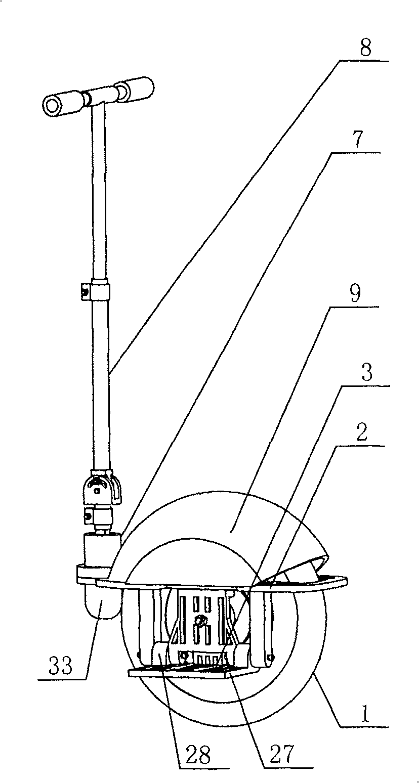
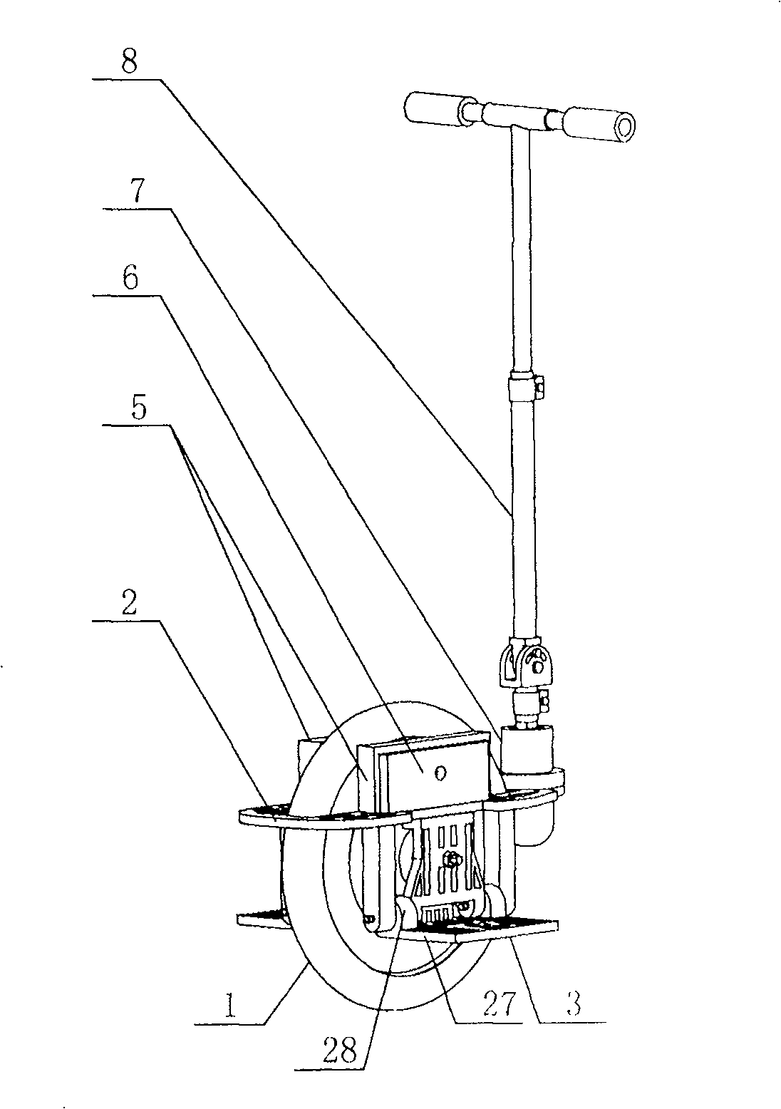
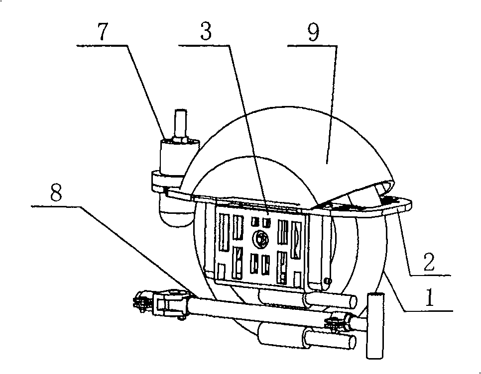
[0007] Specific implementation mode 1: Combination Figure 1~Figure 9 To describe this embodiment, this embodiment consists of a walking wheel 1, a motor 52, a reducer 53, a vehicle body platform 2, a foot pedal 3, an electrical connection 4, a battery 5, a first circuit board 6, a sensor 7, and an armrest 8. , The upper cover 9, the first connecting shaft 10; the motor 52 and the reducer 53 are fixed in the hub 11 of the walking wheel 1, the output end of the motor 52 and the input end of the reducer 53, the reducer 53 The output end of the travel wheel 1 is fixedly connected to the spokes or spokes 12, the vehicle body platform 2 is sleeved on the travel wheel 1 and fixed to the motor shaft 13, and the two sides of the travel wheel 1 and the vehicle body platform 2 The battery 5 and the first circuit board 6 fixedly connected to the vehicle body platform 2 are installed in the cavity between the two. The power input end of the motor 52 is connected to the first circuit board 6 t...
specific Embodiment approach 2
[0008] Specific implementation manner two: combination Figure 7 To illustrate this embodiment, the traveling wheel 1 of this embodiment is composed of a hub 11, spokes or spokes 12, and a rim 14. The hub 11 is located in the center of the rim 14, and the hub 11 (the output end of the reducer) and the rim 14 The spokes or spokes 12 evenly distributed along the circumference of the rim 14 are fixed between them, and the walking wheel 1 may adopt an integral structure or a split structure. With this arrangement, the structure is simple, and the use is safe and reliable. The speed reducer 53 drives the walking wheel 1 to rotate. The traveling wheel 1 can also be purchased from outside. The manufacturer integrates the motor 52 and the reducer 53 into the hub 11 of the traveling wheel 1. The other components and connection relationships are the same as in the first embodiment.
specific Embodiment approach 3
[0009] Specific implementation mode three: combination Figure 10 ~ Figure 12 Explaining this embodiment, the armrest 8 of this embodiment is composed of a grip rod 15 and a "T"-shaped rod 16, a connecting rod 17, a connecting member 18, a second connecting shaft 19, a locking pin 100, and a clamp 20; The holding rod 15 is composed of a metal cannula 21 and a soft sleeve 22. The connecting member 18 is composed of a connecting socket 23 and a connecting socket 24. The bottom end surface of the connecting socket 23 and the upper end surface of the connecting socket 24 For fixed connection, the two ends of the horizontal cross bar 25 of the T-shaped rod 16 are respectively inserted into one end of the metal insert tube 21, and the other end of the metal insert tube 21 is inserted into one end of the soft sleeve 22. The lower end of the T-shaped rod 16 is installed in the inner hole at the upper end of the connecting rod 17, the lower end of the connecting rod 17 is provided with a c...
PUM
 Abstract
Description
Claims
Application Information
 - R&D
- Intellectual Property
- Life Sciences
- Materials
- Tech Scout
- Unparalleled Data Quality
- Higher Quality Content
- 60% Fewer Hallucinations
Browse by: Latest US Patents, China's latest patents, Technical Efficacy Thesaurus, Application Domain, Technology Topic, Popular Technical Reports.
© 2025 PatSnap. All rights reserved.Legal|Privacy policy|Modern Slavery Act Transparency Statement|Sitemap|About US| Contact US: help@patsnap.com