
Fast slip casting technique between composite well wall

A technology of grouting system and shaft wall, which is applied in the direction of sinking, shaft equipment, mining equipment, etc., can solve the problems of poor safety conditions, small space, low efficiency, etc., and achieve fast grouting speed, prevent water leakage, and high efficiency Effect

Inactive Publication Date: 2009-09-30
盛天宝 +1
View PDF2 Cites 0 Cited by
  • Summary
  • Abstract
  • Description
  • Claims
  • Application Information

AI Technical Summary

Problems solved by technology

Construction on the hanging pan, the grouting materials and personnel need to be lifted vertically, the space is small, the safety conditions are poor, the efficiency is low, and the cost is high

Method used


Image

  • Fast slip casting technique between composite well wall
  • Fast slip casting technique between composite well wall

Examples


Embodiment 1

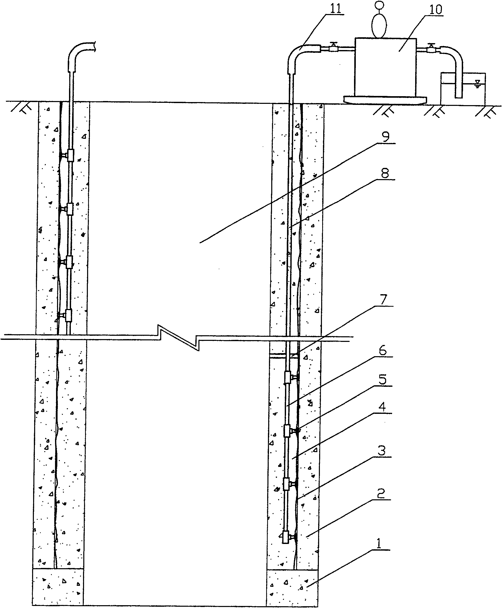
[0011] Depend on figure 1 As shown, the composite well wall is composed of the outer well wall 2, the inner well wall 4, and the plastic interlayer wall 3. The grouting pump 10 is fixed on the surface of the wellhead. Before grouting, the wellbore is segmented according to the depth of the frozen wellbore, the thickness of the well wall, the strength, and the level of the aquifer. Generally, the wellbore is divided into 1-4 grouting segments. The section height is generally 100-200m. When constructing the inner shaft wall 4, the vertical section grouting pipe 6 suitable for the height of the grouting section is preset and pre-embedded, and the section grouting pipe 6 is set inside In the well wall of each layer, the preset and pre-embedded vertical segmented grouting pipes are sequentially carried out upwards from above the wall seat 1. A number of grouting heads 5 are arranged on the segmented grouting pipe 6, and the distance between the grouting heads 5 is 5-7 meters. The ...

Embodiment 2

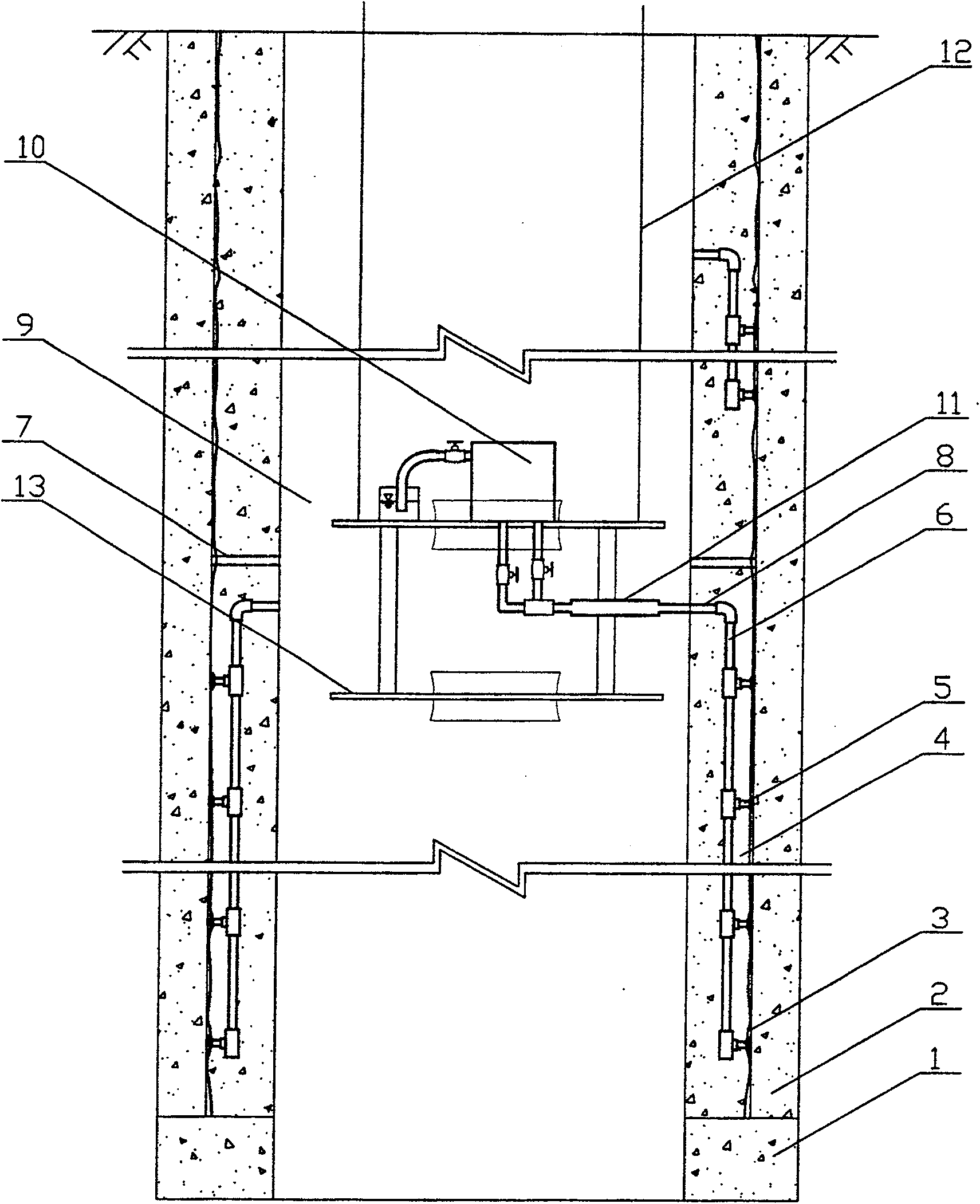
[0013] Depend on figure 2 As shown, the composite well wall is composed of the outer well wall 2, the inner well wall 4, and the plastic interlayer wall 3. The grouting pump 10 is fixed on the hanging pan 13 in the wellbore 9, and the hanging pan 13 is pulled by four hanging pan wire ropes 12. Slurry segmentation, generally divide the wellbore into 2-3 grouting segments, and the segment height is generally 100-200m. When constructing the inner well wall 4, the preset, pre-embedded and grouting segment heights are suitable The vertical segmental grouting pipe 6 is arranged in the inner shaft wall 4, and the vertical segmental grouting pipes are preset and pre-embedded starting from above the wall seat 1 and proceeding upwards sequentially. A plurality of grouting heads 5 are arranged on the segmented grouting pipe 6, and the distance between the grouting heads is 5-7 meters. The grouting heads 5 communicate with the plastic interlayer walls 3, and multiple grouting points are...


PUM


Abstract

The invention discloses a rapid injection technique to cavity among walls of compound shaft. The shaft is sectioned by injection in accordance with the frozen shaft depth, shaft wall thickness and strength and stratigraphic position of water-bearing bed, and the section has height of 100-200 m. When constructing inner layer shaft wall, pre-installing and pre-embedding a vertical sectioned injection pipe adaptable to the height of the injected section, a plurality of injection heads are equipped on the sectioned injection head and communicated with the cavity among walls of plastic interlayer, a plurality of injection points are formed at the same time at one section, the upper end of the sectioned injection pipe is connected with a delivery pipe, and the other end of the delivery pipe is connected with an injection pump via a connecting rubber pipe. The invention has the advantages of simple process, safe and reliable performance, high injection speed, high efficiency, and low cost. And, the occupied time of injection process to cavity among walls to the shaft construction is reduced by 60-90 percent, so as to shorten the shaft construction period.

Description

Technical field: [0001] The invention belongs to the technical field of interwall grouting for drilling composite wells by freezing method. Background technique: [0002] Freeze sinking is the main special construction method used to build wells through deep topsoil aquifers. More than 500 mine vertical shafts have been built using the freezing method in China, and more than 30 frozen shafts are under construction. At present, the thickness of the shaft passing through the topsoil layer and the freezing depth have reached 528m and 628m. The frozen shafts are mostly made of mixed soil and reinforced concrete. Suspicious soil plastic interlayer composite shaft wall structure. The freezing and sinking construction process includes: ①drilling and freezing; ②excavating the wellbore and building the outer well wall in sections from top to bottom; ③excavating wall seats; ④laying plastic plates and covering the inner well wall from bottom to top; ⑤ Grouting between plastic interla...

Claims


Application Information

Patent Timeline
Patent Type & Authority Patents(China)
IPC IPC(8): E21D1/12
Inventor 盛天宝白云来王俊臣魏世义陈新明田亚军祁书峰
Owner 盛天宝
Learn More