Projection type optical system structure

An optical system and projective technology, which is applied in the field of projective optical system structure, can solve the problem that the vehicle lamp system is huge, and the brightness of the light-emitting diode 412 cannot reach the brightness of the car bulb, so as to avoid the effect of being too large

Inactive Publication Date: 2009-10-14
T Y C BROTHER IND CO LTD
View PDF3 Cites 0 Cited by
  • Summary
  • Abstract
  • Description
  • Claims
  • Application Information

AI Technical Summary

Problems solved by technology

[0006] However, the brightness of the light-emitting diodes 412 currently on the market still cannot reach the brightness of ordinary car bulbs, and the projection optical system 4 of the multi-light source system must be used (such as image 3 shown) to form an optical system that complies with relevant regulations; the projection optical system 4 of the multi-source system must be at least two sets of projection optical systems 4 to form a vehicle lamp, and the multiple sets of independent The projected optical system4 will lead to a large overall system of automotive lamps

Method used


Image

  • Projection type optical system structure
  • Projection type optical system structure
  • Projection type optical system structure

Examples


Embodiment Construction

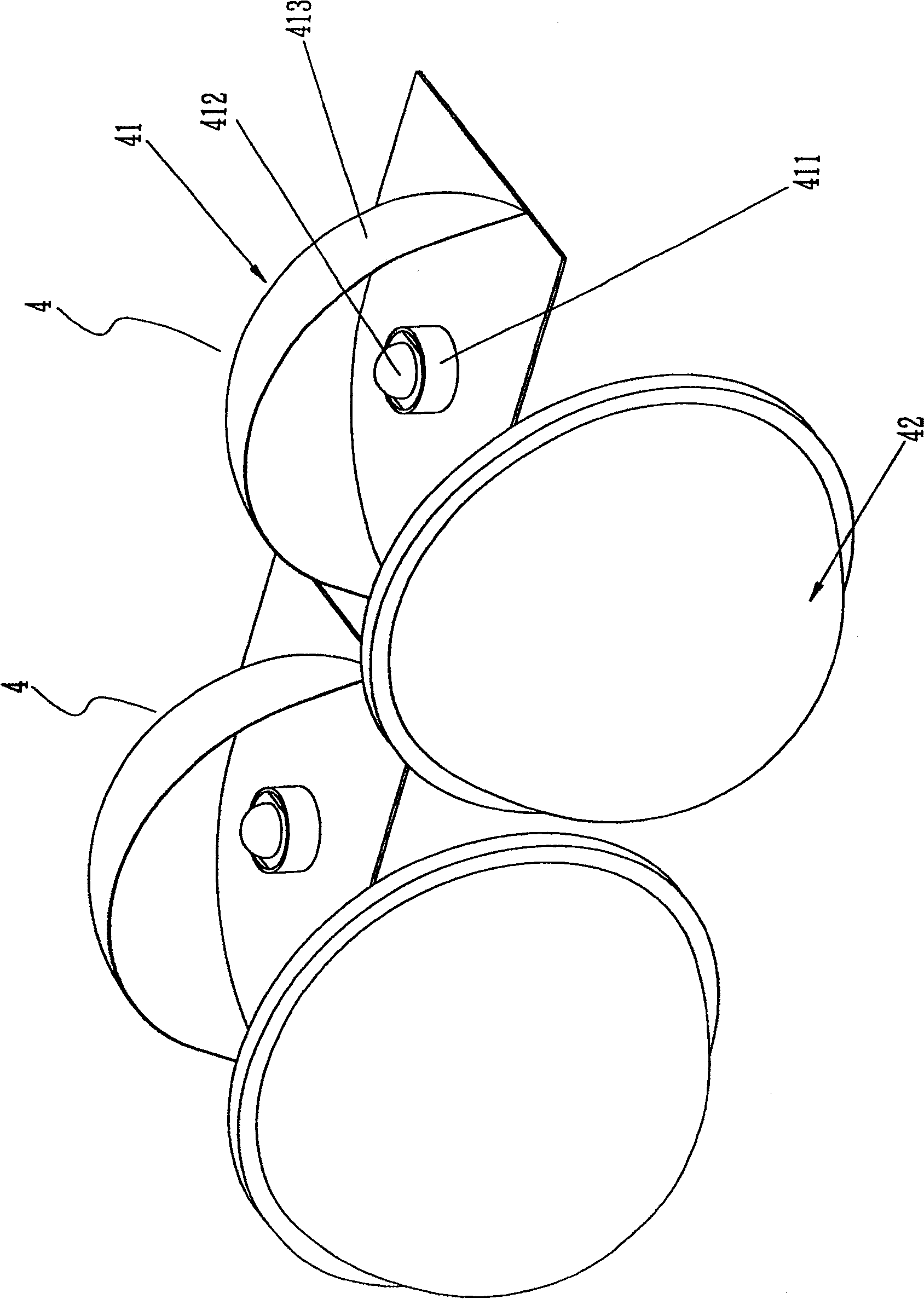
[0030] First, see Figure 4 and Figure 5 As shown, it is a three-dimensional appearance and an exploded schematic view of the projection optical system 5; the projection optical system 5 can be used in a vehicle headlight device, and it mainly includes a light source group 51 and a lens body 52; wherein,

[0031] The light source group 51 includes a fixed seat 511, at least two light emitting diodes 512 and a reflector body 513; the fixed seat 511 includes a base plate 5111 and at least two base bodies 5112, and the base body 5112 is protruded on the base plate 5111 , the base body 5112 is fixed for the light emitting diode 512; the light emitting diode 512 is fixed on the base body 5112 of the fixing seat 511; the reflector body 513 is fixed on the substrate 5111 of the fixing seat 511, and the The reflector body 513 has at least two continuous arc surfaces 5131 similar to ellipsoids on its top surface, and the two sides of the reflector body 513 are respectively cut planes...


PUM


Abstract

The invention relates to a projection optics system, applied in head lamp device used in car, mainly comprising lighting source group consisted of fixed seat, light emitting diode and reflection mirror; lens fixed at front of lighting source group. As the left-right sides of lens are cut the cross section is formed so as to make the width of lens narrow in the level. When multiple lighting source system is consisted of lighting emitting diode multiple lens are kept close so as to form a multiple lighting source system with tighter and smaller space. Too huge optics system is avoided.

Description

technical field [0001] The invention relates to a projective optical system structure, in particular to a projective optical system structure which uses a light emitting diode as a light source of the projective optical system and is applied to a vehicle lamp. Background technique [0002] Safe, high-efficiency, and streamlined vehicle lamps have always been the research and development goals of vehicle lights. Through the assistance of vehicle lights, drivers can clearly understand the road conditions and reduce the danger and discomfort of glare to other vehicles and pedestrians. [0003] Existing automotive lamps, especially automotive headlights, have mostly used the existing projection optical system 1. The main components of the projection optical system 1 include a light source group 11 and a lens body 12, such as figure 1 As shown, the light source group 11 is composed of a luminous body 111 and a mirror body 112; please refer to figure 2 As shown, the light path p...

Claims


Application Information

Patent Timeline
Patent Type & Authority Patents(China)
IPC IPC(8): F21S8/10F21V7/00F21V5/04F21V13/00G02B3/08F21W101/10F21Y101/02F21Y115/10
Inventor 吴享珍
Owner T Y C BROTHER IND CO LTD
Why Eureka
Try Eureka