Fuel oil saving device of vehicle

A fuel and vehicle technology, applied in the charging system, combustion engine, fuel air filter, etc., can solve the problems of greatly reduced efficiency, obvious carbon black, carbon black emission, etc., to achieve simple installation and debugging, avoid peroxygen Combustion and exhaust emission reduction effect

Inactive Publication Date: 2010-10-20
姚大华
View PDF5 Cites 7 Cited by
  • Summary
  • Abstract
  • Description
  • Claims
  • Application Information

AI Technical Summary

Problems solved by technology

The single use of the fuel magnetization processor on the engine can save fuel and reduce emissions, but the fuel is magnetically excited to produce more free carbon, and more oxygen must be combined with it to participate in combustion, otherwise the free carbon will If it does not react with oxygen at high temperature, it will become carbon black emission, but why can't we see carbon black in the exhaust gas? Because modern vehicles are equipped with emission purification devices at the rear, a small amount of carbon black can be absorbed by the emission purification device, so there is no obvious carbon black in the exhaust gas
However, the emission purification device has a lifespan. Once the emission purification device fails after a long time, the carbon black in the exhaust gas will be quite obvious.
On the other hand, when it comes to fuel-saving efficiency, in practice, the effect of the newly installed magnetized processor is more obvious in the first month or two, but in the third month or longer,

Method used


Image

  • Fuel oil saving device of vehicle
  • Fuel oil saving device of vehicle
  • Fuel oil saving device of vehicle

Examples


Example Embodiment

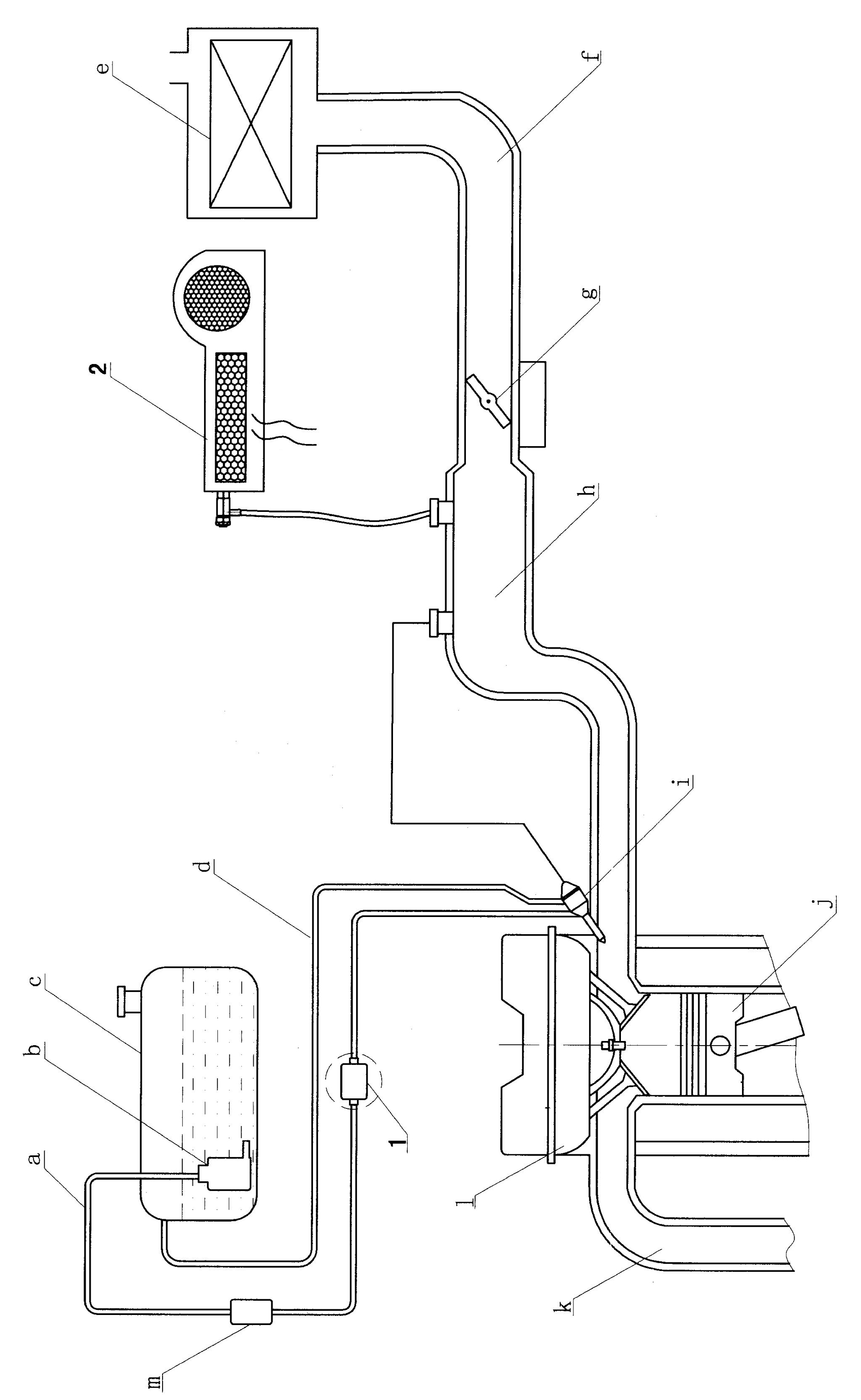
[0033] Depend on Figures 1 to 13 It can be seen that the vehicle fuel saving device of the present invention includes a fuel magnetization processor, and is characterized by:

[0034] The fuel-saving device is composed of two groups, one group is the fuel magnetization processor 1 arranged on the engine oil inlet pipeline, and the other group is the oxygen-enhancing and oxygen-supplying device 2 installed on the engine inlet end or the vacuum pipe, wherein:

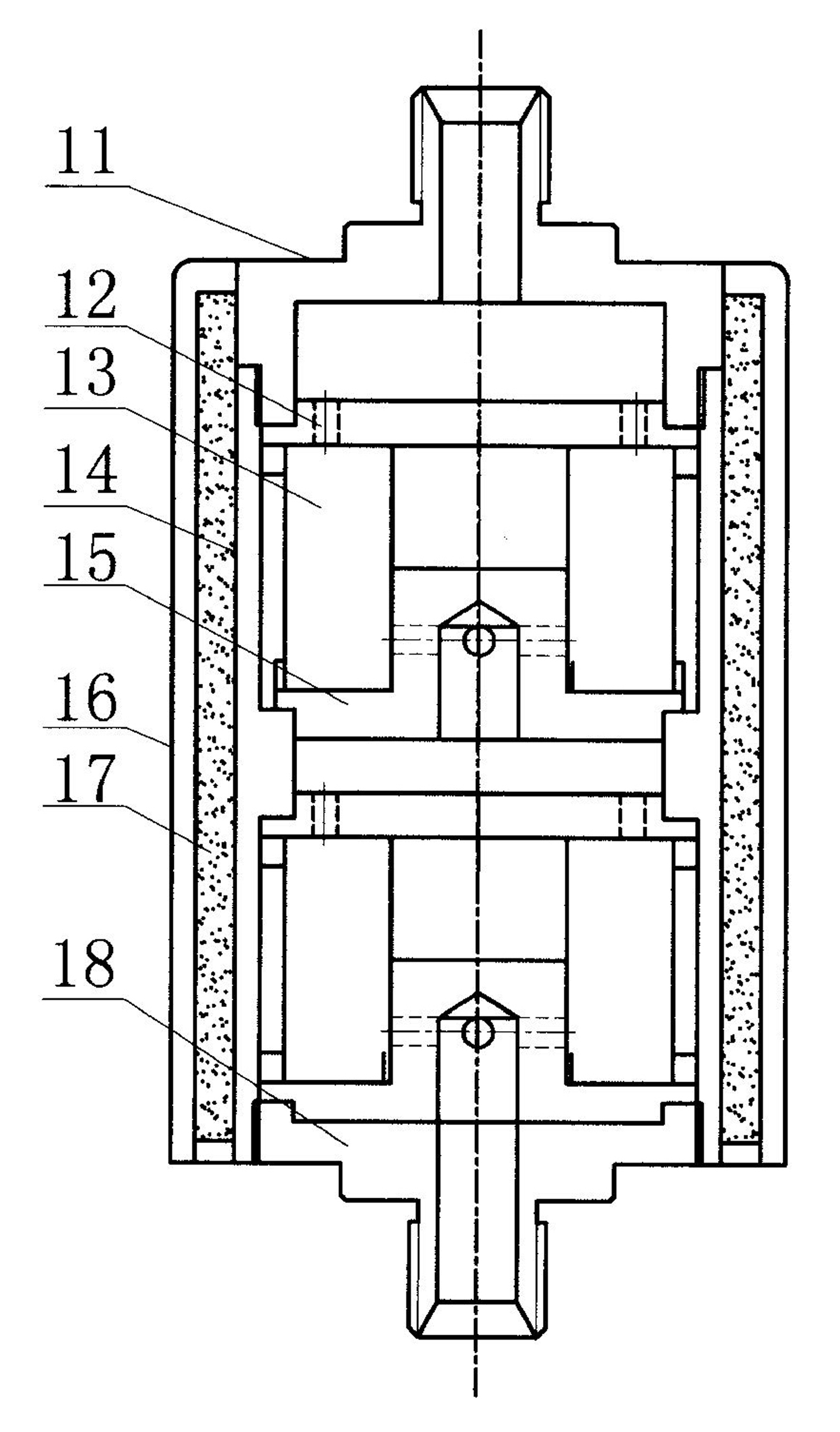
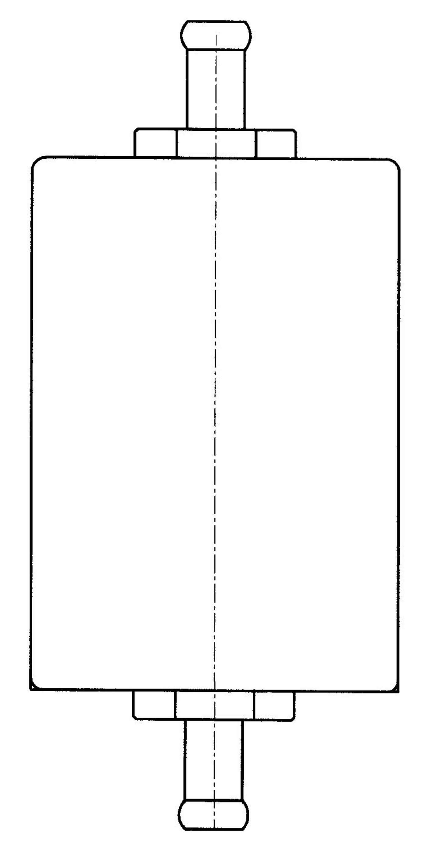
[0035] The fuel magnetization processor includes a main body 14 composed of two multi-gradient magnetization radiation areas, two retention areas and an output port. The magnet 13 is formed, and two magnetic energy radiation areas are set adjacent to each other, the inlet end of the first magnetic energy radiation area is the first retention area, and the second retention area is between the two magnetic energy radiation areas;

[0036] The oxygen-enhancing and oxygen-supplying device is composed of an air separator and...


PUM


Abstract

The invention relates to a fuel oil saving device of a vehicle, comprising two groups, i.e. a fuel oil magnetization processor and an oxygen increasing and supplementing device, wherein the fuel oil magnetization processor comprises two multi-gradient magnetization radiation areas, two stagnation areas and an output port, wherein each multi-gradient magnetization radiation area consists of a main body; each magnetic energy radiation area comprises an upper supporting plate, a lower supporting plate and a permanent magnet clamped between the upper supporting plate and the lower supporting plate, and the two magnetic energy radiation areas are arranged adjacently; the inlet end of the first magnetic energy radiation area is the first stagnation area, and a second stagnation area is positioned between the two magnetic energy radiation areas; the oxygen increasing and supplementing device comprises a space divider and an ozone generator, wherein the space divider comprises an air filter assembly, a fan assembly, a permanent magnet fastening end cover clamped between the upper supporting plate and the lower supporting plate, and the like and forms an integer with a shell; and a space divider assembly control power supply inside the ozone generator, a booster, a generating tube and a boosting pump are sequentially arranged on a base plate. The invention has high fuel oil saving efficiency and easy installation and debugging.

Description

technical field [0001] The invention relates to a fuel-saving and environmental protection technology for a vehicle fuel engine, in particular to a fuel-saving device for vehicle fuel. Background technique [0002] At present, most or most of all vehicles still use gasoline or diesel as the raw material of the engine. Due to the inability to burn more fully, the exhaust emissions more or less cause certain environmental pollution to the atmosphere. Especially after the power and combustion efficiency of the engine decline, it becomes more serious. People are constantly seeking some new technologies and methods, and formulating new environmental protection standards to control the environmental pollution. But it doesn't solve the underlying problem. The single use of fuel magnetization processor on the engine can save fuel and reduce emissions to a certain extent, but the fuel is magnetized to generate more free carbon, and more oxygen must be combined with it to participat...

Claims


Application Information

Patent Timeline
IPC IPC(8): F02M27/04F02M27/06F02M25/12F02M35/06
CPCY02T10/126Y02T10/121Y02T10/12
Inventor 姚大华
Owner 姚大华
Why Eureka
Try Eureka