Light source device

A light source device, visible light technology, applied in the direction of light source, electric light source, projection device, etc., to achieve the effects of enhanced damage resistance, good cooling effect, and improved mechanical strength

Inactive Publication Date: 2009-10-14
USHIO DENKI KK
View PDF9 Cites 0 Cited by
  • Summary
  • Abstract
  • Description
  • Claims
  • Application Information

AI Technical Summary

Problems solved by technology

In addition, the miniaturization of the liquid crystal display panel itself, which is the object to be irradiated, is also one of the reasons why the miniaturization of the light source device is required.

Method used


Image

  • Light source device
  • Light source device
  • Light source device

Examples


Embodiment Construction

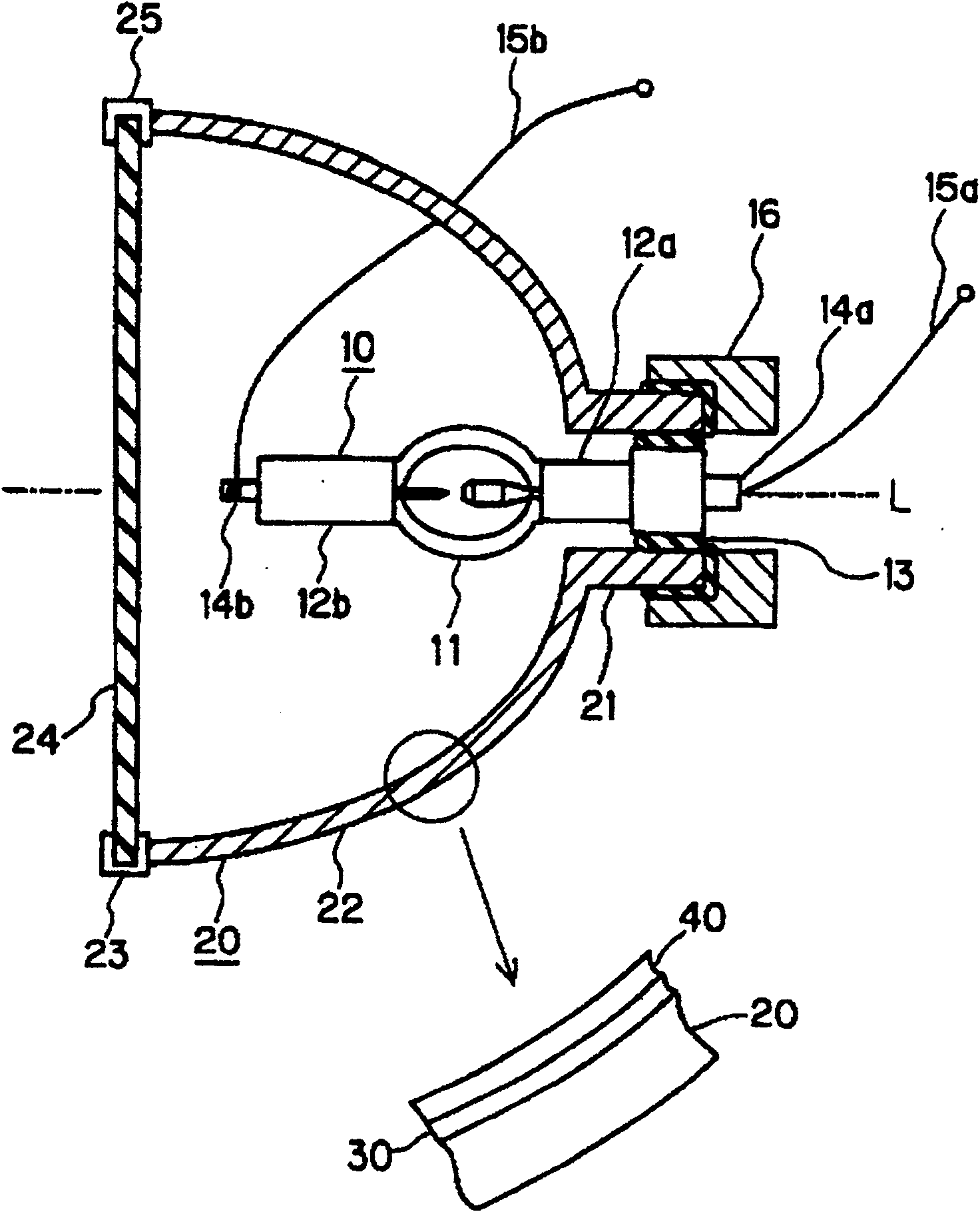
[0027] figure 1 A schematic configuration diagram illustrating a light source device of the present invention is shown.

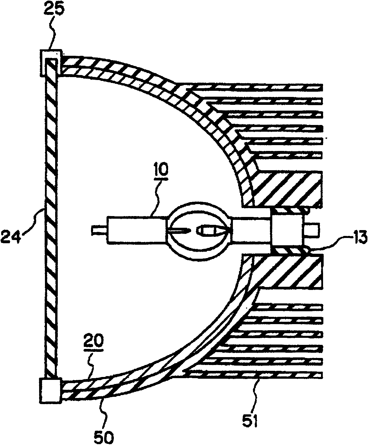
[0028] The light source device is composed of a short-arc ultra-high pressure discharge lamp 10 (hereinafter also referred to as "discharge lamp") and a concave reflector 20 surrounding the discharge lamp 10. The optical axis L of the concave reflector 20 and the arc direction of the discharge lamp 10 are approximately Consistently, the arc bright spot of the discharge lamp 10 and the first focal point of the concave reflector 20 are configured to be consistent at the same time.

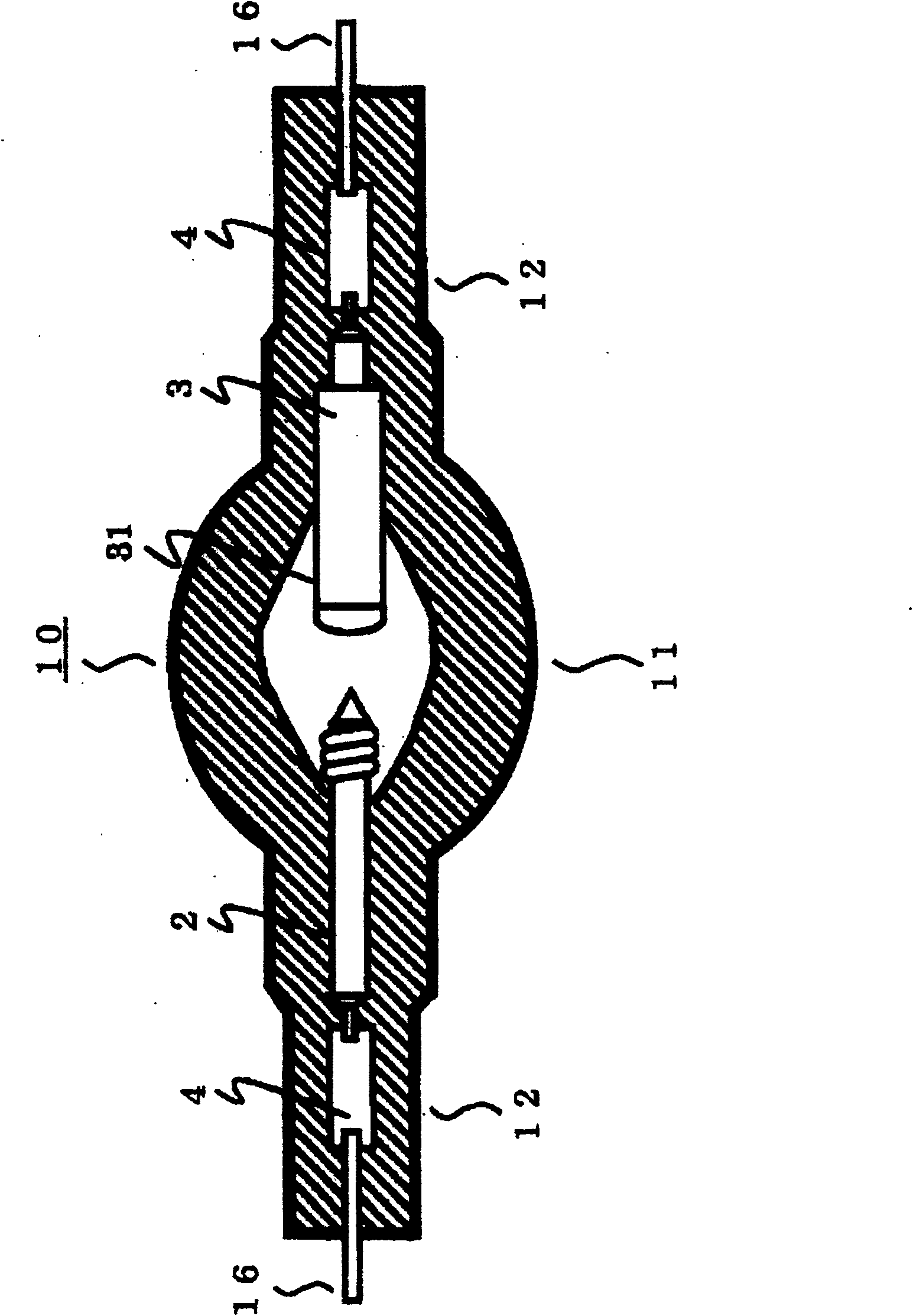
[0029] The discharge vessel of the discharge lamp 10 is composed of a substantially spherical light emitting portion 11 and rod-shaped sealing portions 12a and 12b extending along both ends of the light emitting portion 11 , and a pair of opposing electrodes are arranged inside the light emitting portion 11 . The sealing portion 12 a of the discharge lamp 10 is inserted into the ...


PUM


Abstract

PROBLEM TO BE SOLVED: To provide a light source improved in its mechanical strength and coated without distorting the visible light reflector film. SOLUTION: This light source consists of a high pressure discharge lamp 10 and a concave surface mirrors 20 enclosing it. The concave surface mirror 20 is composed of a base consisting of copper, iron or their alloy, an intermediate layer 30 disposed on the inside surface of the above base with a heat absorbing function and a reflection surface smoothing function, and a visible light reflector layer 40 made of a multilayer dielectric film 40 disposed on the above intermediate film. COPYRIGHT: (C)2005,JPO&NCIPI

Description

technical field [0001] The invention relates to a light source device composed of a high-pressure discharge lamp and its concave reflector. In particular, it relates to a light source device used in a projection device such as a liquid crystal display device or a DLP (digital light processor) of a DMD (digital mirror device) in which 0.25 mg / mm 3 The above-mentioned mercury, the ultra-high pressure mercury lamp whose mercury vapor pressure becomes ultra-high pressure when lighting the lamp is used as the light source. Background technique [0002] Projection-type projection devices require uniform illumination of images on a rectangular screen and require high color rendering. Therefore, a metal halide lamp in which mercury or metal halide is sealed is used as a light source. And with the development of the times, metal halide lamps are now further miniaturized and point light sources, and products with extremely small distances between electrodes have also appeared in pra...

Claims


Application Information

Patent Timeline
Patent Type & Authority Patents(China)
IPC IPC(8): G03B21/20G03B21/14G02B5/10H01J61/00F21S2/00F21V7/00F21V7/22F21V15/00F21V25/12F21V29/00F21V29/505F21Y101/00H01J61/20
Inventor 岩林弘久
Owner USHIO DENKI KK
Why Eureka
Try Eureka