Loading and unloading system and its loading and unloading method for self unloading binding overhead torch

A loading and unloading system and self-unloading technology, applied in the direction of combustion method, gas fuel burner, combustion type, etc., can solve the problems of potential safety hazards, increase the floor space and protection area of ​​the flare system, and the lack of guide rails and stabilization measures for the flare head. , to achieve the effect of reducing the protection area and saving land area

Inactive Publication Date: 2009-10-21
NO 711 RES INST CHINA SHIPPING HEAVY IND GRP
View PDF5 Cites 0 Cited by
  • Summary
  • Abstract
  • Description
  • Claims
  • Application Information

AI Technical Summary

Problems solved by technology

[0003] The Chinese utility model patent No. 03214413.X, titled "a tower-type venting flare tip replacement device" discloses a traditional elevated flare tip replacement device, wherein a load-bearing device is installed on the flare tower Rotary hanger, and equipped with a slewing device installed outside the hanger, fixed pulley and guide wheel are installed on the upper part of the hanger, one end of the wire rope installed on the fixed pulley and guide wheel has a hook, and the other end is installed on the hoist, There is also a fixed hanger installed on the flare tower frame, and a manual rewinding chain is installed on the upper part of the fixed hanger. When the torch head is replaced, the hook on the wire rope and the lifting mechanism on the manual rewinding chain are respectively hung on the top of the torch head. First, remove the torch head to be replaced from the chimney by manpower, and hoist it to the ground through the action of the hoist, and then lift the new torch head to the position of the original torch head through the hook, and rely on manpower to position and place it. It is fixed on the chimney. In addition, the rotation of the hanger is also completed by manpower; therefore, the replacement device for this type of torch head can only be applied to a single torch, or there are no guide rails and stabilizing measures when disassembling the torch head. considerable security risk
However, for bundled elevated flares, when one of the bundled flares is in working condition, personnel cannot approach the top of the flare to maintain or overhaul other faulty flares, that is to say, all flares must be repaired at the same time conduct
[0004] Due to the constraints of the above problems, for multiple flares that cannot be overhauled at the same time, they can only be arranged separately, that is, each flare is supported by a tower, and each flare needs to be separated by a certain distance, which greatly increases the construction of the flare system investment, also increases the footprint and protection area of ​​the flare system

Method used


Image

  • Loading and unloading system and its loading and unloading method for self unloading binding overhead torch
  • Loading and unloading system and its loading and unloading method for self unloading binding overhead torch
  • Loading and unloading system and its loading and unloading method for self unloading binding overhead torch

Examples


Embodiment Construction

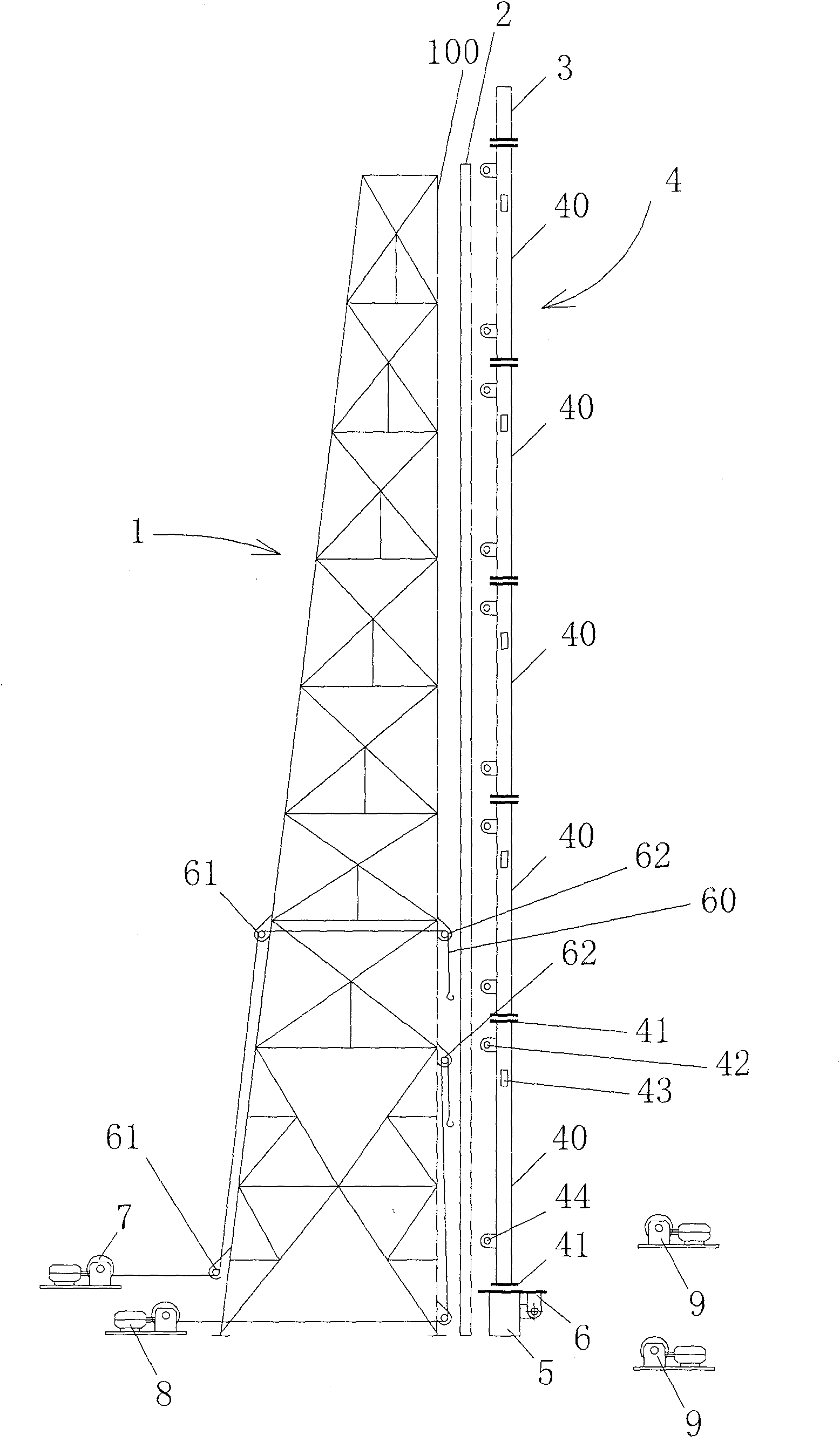
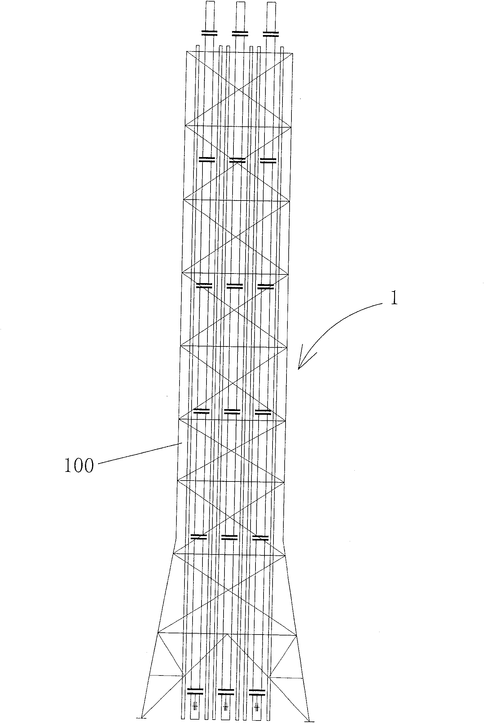
[0037] figure 1 The self-unloading bundled elevated flare and its loading and unloading system of the present invention are shown.

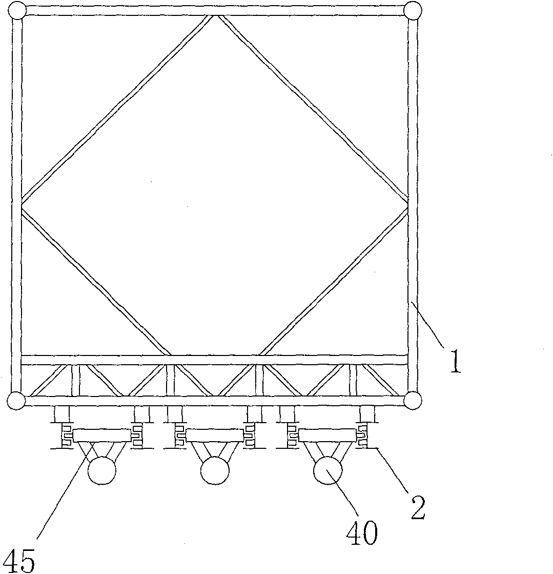
[0038] Such as figure 1 and figure 2 As shown, the flare tower 1 has a vertical side 100 , and the flare barrel 4 is arranged on the side 100 of the tower.

[0039] refer to figure 1 , the torch cylinder 4 is composed of independent multi-section cylinders 40. In this embodiment, the number of sections of the torch cylinder 4 is 5, and the order from bottom to top is the first section, the second section, ... , paragraph 5. Both ends of each cylinder 40 are provided with flanges 41 , and the cylinders 40 of each section are connected by flanges 41 . The flare head 3 is placed on the upper end of the cylinder body 40 of the fifth section and is connected with the cylinder body 40 through the flange 41 provided at the bottom thereof.

[0040]The bottom of the torch cylinder 4 is provided with a basic support 5, and the basic support 5 is pro...


PUM


Abstract

The invention provides a loading and unloading system for a self-unloading bundled elevated torch, the torch includes a torch head and a torch cylinder composed of multiple sections of cylinders, and each section of the cylinder is respectively provided with a first end connection between the cylinders at both ends. A connecting element, the bottom of the flare head is provided with the first connecting element; its loading and unloading system includes a hoist, a tower, a rope and the flare and guide rails arranged on the side of the tower, and each section of the barrel of the flare includes a The support element that the guide rail is slidably connected; The hoist wherein comprises the hoist hoist that is used to lift every section cylinder body, and each section cylinder body includes the second connection element that is used to be connected with hoist hoist by rope; The present invention also provides a A method for loading and unloading the elevated torch by using the loading and unloading system, that is, loading and unloading the torch barrel and the torch head of the elevated torch in sections, thereby realizing the centralized bundling of multiple torches, and meeting the maintenance work of the faulty torch without affecting other torches combustion.

Description

technical field [0001] The invention relates to a loading and unloading system and a loading and unloading method of an elevated flare, in particular, to a loading and unloading system and a loading and unloading method of an elevated flare that is used for multiple sets of bundling and sharing a tower support. Background technique [0002] At present, the most widely used torches in oil refining and chemical enterprises are tower-supported elevated torches. When multiple torches need to be installed, in order to save land, reduce the thermal radiation protection area of ​​the torch, and facilitate the centralized management of the torch, it is usually considered to bundle multiple torches, that is, multiple torches share a tower support. [0003] The Chinese utility model patent No. 03214413.X, titled "a tower-type venting flare tip replacement device" discloses a traditional elevated flare tip replacement device, wherein a load-bearing device is installed on the flare towe...

Claims


Application Information

Patent Timeline
Patent Type & Authority Patents(China)
IPC IPC(8): F23D14/38
Inventor 张世程朱国庆刘世俊奚文杰刘柏镛陈斌曹枫
Owner NO 711 RES INST CHINA SHIPPING HEAVY IND GRP
Why Eureka
Try Eureka