Electronic ballast of high strength gas discharging light

A technology for electronic ballasts and gas discharge lamps, applied in the use of gas discharge lamps, electric light sources, electrical components, etc., can solve the problems of many components, high cost, complex structure, etc., achieve high power factor, enhance stability to ensure the effect of output light effect

Inactive Publication Date: 2009-10-21
ZHEJIANG UNIV
View PDF3 Cites 0 Cited by
  • Summary
  • Abstract
  • Description
  • Claims
  • Application Information

AI Technical Summary

Problems solved by technology

[0004] The traditional three-stage low-frequency square wave circuit is composed of a power factor correction stage, a DC-DC conversion stage, and a low-frequency inverter stage that generates a low-frequency square wave. Although this circuit can effectively overcome the occurrence of acoustic resonance, because the circuit has three stages , there are disadvantages such as complex structure, many components and high cost

Method used


Image

  • Electronic ballast of high strength gas discharging light
  • Electronic ballast of high strength gas discharging light
  • Electronic ballast of high strength gas discharging light

Examples


Embodiment Construction

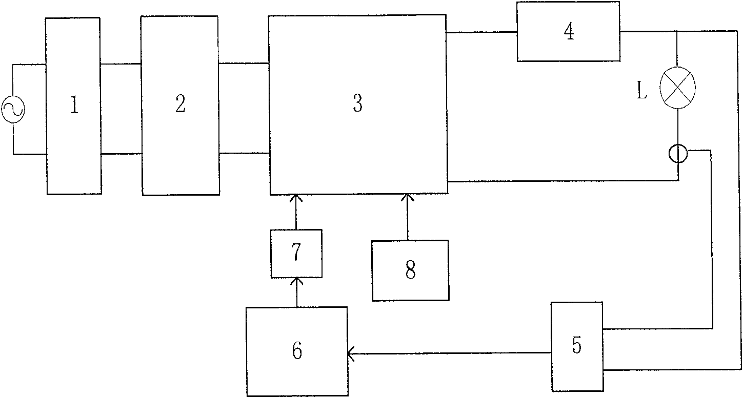
[0020] refer to figure 1 , the high-intensity gas discharge lamp electronic ballast of the present invention includes an electromagnetic interference filter circuit 1, a rectifier bridge 2, a combined single-stage power factor correction and a low-frequency square wave signal generating circuit 3, a high-intensity gas discharge lamp L, and a lamp L provides ignition circuit 4 for high-voltage pulse signal, voltage and current detection circuit 5, constant power control circuit 6, high-frequency switch tube drive circuit 7 and low-frequency drive signal generator 8. The voltage and current signals detected from the lamp L are input to the constant power control circuit 6 after passing through the voltage and current detection circuit 5, and the pulse width of the output drive signal is modulated by the constant power control circuit 6, so that the power output to the lamp L is basically constant .

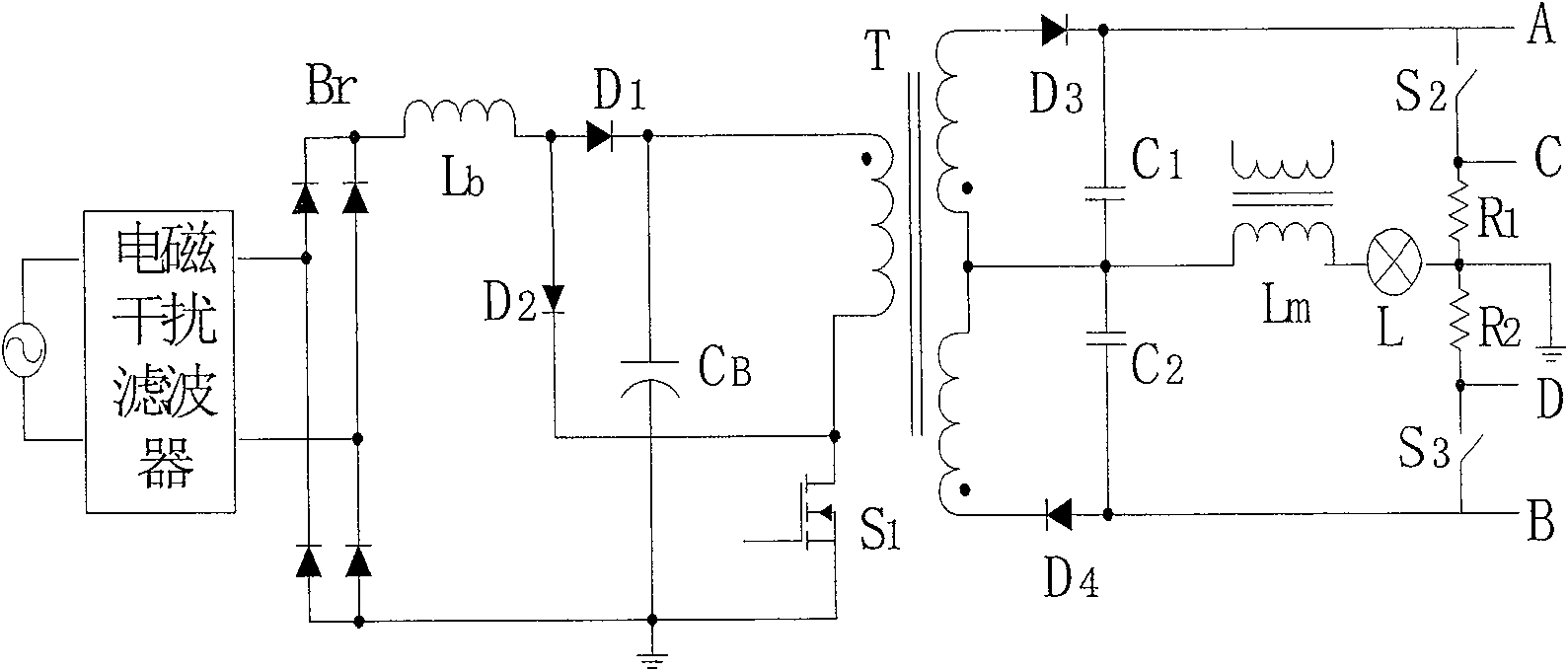
[0021] figure 2 Shown is a circuit example of a combined single-stage power ...


PUM


Abstract

The electronic ballast used for high intensity gas discharge lamp consists of: a combined type circuit for correcting single-stage power factor and generating low frequency square wave signal, a voltage and current testing circui, a constant power control circuit. The voltage and current testing signal obtained from low frequency square wave circuit is inputted into the constant power control circuit to generate a switch-driving signal with a certain pulse width. The constlant power inputted to the lamp is controlled through controlling the duty radio of high frequency switch in the single-stage power factor correction circuit.

Description

Technical field: [0001] The invention relates to an electronic ballast, in particular to an electronic ballast for high-intensity gas discharge lamps such as high-pressure sodium lamps and metal halide lamps. Background technique: [0002] In recent years, high-intensity gas discharge lamps have been more and more widely used due to their high luminous efficiency and long life. Traditional inductive ballasts are bulky and heavy, and the application of high-frequency electronic ballasts meets the requirements of ballast miniaturization. However, the acoustic resonance phenomenon of high-intensity gas discharge lamps operating at high frequencies (generally dozens of kHz to hundreds of kHz) limits the application of high-frequency electronic ballasts. When the acoustic resonance occurs, the lamp arc will be unstable, causing the light output to be unstable, flickering, rolling, and seriously affecting the lighting effect. This phenomenon is especially serious in electronic ba...

Claims


Application Information

Patent Timeline
Patent Type & Authority Patents(China)
IPC IPC(8): H05B41/288
CPCY02B20/202Y02B20/00
Inventor 杨永兵钱照明
Owner ZHEJIANG UNIV
Why Eureka
Try Eureka