Ring type steel corbel node for beam-free building cover connection reinforced concrete post

A technology of reinforced concrete column and beamless floor, applied in the direction of building, building structure, etc., can solve the problems of no more than 18 stories high, large vertical deflection, heavy foundation load, etc., to improve the bending and shearing capacity , the effect of reducing vertical displacement and increasing shear resistance

Active Publication Date: 2009-10-28
ARCHITECTURAL DESIGN RES INST OF GUANGDONG PROVINCE
View PDF4 Cites 0 Cited by
  • Summary
  • Abstract
  • Description
  • Claims
  • Application Information

AI Technical Summary

Problems solved by technology

[0004] (1) The shear performance of slab-to-column joints with beamless floors lacking exposed beam support is still weaker than that of beam-to-column joints with beamed floors;
[0005] (2) The flexural capacity of the slab-column joints of the beamless floor is also weaker than that of the beam-column joints of the beamed floor. The cutting performance has been improved, but it has little effect on the improvement of the flexural performance of the floor and the improvement of the mid-span deflection;
[0006] (3) Since its bending stiffness is smaller than that of beamed floors, the vertical deflection of beamless floors is larger than that of beamed floors, and the deflection is poor, generally up to 20%;
[0007] (4) Due to the above defects, the huge column punching force and bending moment caused by the inability of the beamless floor to resist the earthquake make the connection structure between the beamless floor and the column joints weaker than that of the beamed floor slab-column joints, Poor safety performance;
[0008] (5) Due to the structural defects of the above-mentioned beamless floors, buildings with beamless floors are subject to more restrictions, such as the limit of the highest floor. Generally, buildings with beamless floors must not exceed 18 floors
[0009] (6) In order to improve the strength of the beamless floor, it is often necessary to thicken the thickness of the floor slab, which leads to a waste of materials and labor on the one hand, which significantly increases the construction cost, and also increases the overall weight of the floor and increases the load on the foundation. , further increasing the construction cost of the building

Method used


Image

  • Ring type steel corbel node for beam-free building cover connection reinforced concrete post
  • Ring type steel corbel node for beam-free building cover connection reinforced concrete post
  • Ring type steel corbel node for beam-free building cover connection reinforced concrete post

Examples


Embodiment 1

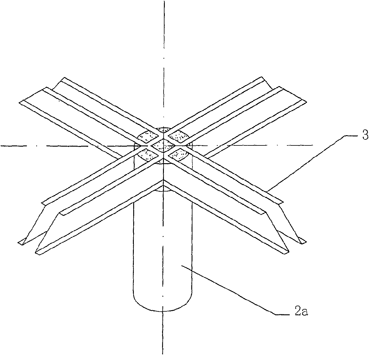
[0042] Figure 6-8 The shown ring-type steel corbel joint for the connection between the beamless floor and the reinforced concrete column is one of the specific embodiments of the present invention, including the reinforced concrete column 2 and the beamless floor 1 at the slab-column joint, And the steel corbel 3 that node place is provided with, there are four steel corbels 3, and the included angle between two steel corbels 3 adjacent to each other is 90 °. The four steel corbels 3 are non-piercing, and intersect to form a well-shaped structure, that is, the steel corbels 3 do not pass through the beamless floor 1, and the upper and lower parts of the beamless floor 1 are provided with criss-crossing Slab gluten 11, steel corbel 3 is provided with column longitudinal reinforcement 21 and column stirrup 22, because it is non-piercing type, column longitudinal reinforcement 21 bends outward along the horizontal direction when extending into beamless floor 1, and Be fixed on...

Embodiment 2

[0044] Figures 9 to 12 The shown ring-type steel corbel joint for the connection between beamless floor and reinforced concrete column is the second specific embodiment of the present invention. The difference from the previous embodiment is that the steel surrounding the reinforced concrete column 2 The number of rings is two circles, which are two inner and outer steel rings, wherein the steel ring on the inner side is tightly bound to the column, and the width of the lower ring plate 42a on the steel ring is greater than the width of the upper ring plate 41a; The radial widths of the upper and lower ring plates 41b, 42b on the steel ring are the same. The distance between two adjacent rings of steel rings is 1.5 to 2.5 times the height of the hidden beams of the floor.

Embodiment 3

[0046] Figure 13 , 14 The shown ring-type steel corbel joint for connecting beamless floors and reinforced concrete columns is the third specific embodiment of the present invention. The difference from the previous embodiment is that the steel corbel 3 is a through-core formula, that is, the steel corbel 3 passes through the beamless floor 1. Other structures are the same as in Embodiment 2.


PUM

PropertyMeasurementUnit
thicknessaaaaaaaaaa

Abstract

A ring-type steel corbel joint connecting a reinforced concrete column with a beamless floor, including a reinforced concrete column at a slab-column joint and a beamless floor, and a steel corbel set at the joint, within the thickness of the floor slab , between every two adjacent steel corbels, at least one steel ring is fixedly connected to the steel corbels on both sides, and the steel corbels are combined to form at least one steel ring around the reinforced concrete column, at least one of which is Steel hoops around the posts. Such a node structure has orthogonal radial steel corbels floating out from the steel ring, and the inner ring steel ring hoops the reinforced concrete column at the node, and works together with the steel corbel to form a circular radial shape. The invisible rigid column cap of the cantilever structure increases the reliable connection of the slab-column, improves the bending resistance and shear resistance of the node; when there is more than one steel ring, it can also effectively reduce the deflection of the mid-span slab.

Description

Technical field [0001] The invention relates to a connection node between a beamless floor and a column, in particular to a ring-type steel corbel node for connecting a beamless floor to a reinforced concrete column, which can effectively improve the bending strength and shear resistance of the node. Background technique [0002] The main feature of the beamless floor is that the floor slab is directly supported on the column, and there is no main beam and secondary beam, so it has (1) a smaller building height than a beamed floor while maintaining the same clearance height, which can be effectively It is more economical to increase the floor height; (2) The flat ceiling has a good sense of space, and the lighting, ventilation and sanitation conditions are better than that of the beamed floor; (3) The formwork is simple, which can save the amount of formwork and simplify construction. It is often used in architectural design, especially in projects with heavy bearing and hig...

Claims


Application Information

Patent Timeline
Patent Type & Authority Patents(China)
IPC IPC(8): E04B1/18E04B1/38
Inventor 陈星邓汉荣林景华李欣赖鸿立向前许振刚何锦超蒋运林徐静郭伟杰王金锋蔡凤维张帆叶国认
Owner ARCHITECTURAL DESIGN RES INST OF GUANGDONG PROVINCE
Why Eureka
Try Eureka