Shaft sealing mechanism and turbine

A shaft seal, thin plate technology, applied in the direction of engine sealing, mechanical equipment, engine components, etc., can solve the problems of thin plate wear and heat, and achieve the effect of preventing heat generation, preventing wear and improving air pressure distribution.

Active Publication Date: 2009-10-28
MITSUBISHI HEAVY IND LTD
View PDF8 Cites 2 Cited by
  • Summary
  • Abstract
  • Description
  • Claims
  • Application Information

AI Technical Summary

Problems solved by technology

This point is different from the conventional example. Due to the difference in air pressure distribution, a pressing force is generated on the thin plate, and the problem that occurs is that the inner peripheral free end 123 contacts the rotor outer surface 4a, and wear and heat generation of the thin plate occur ( Details will be described later)

Method used


Image

  • Shaft sealing mechanism and turbine
  • Shaft sealing mechanism and turbine
  • Shaft sealing mechanism and turbine

Examples


Embodiment Construction

[0039] Embodiments of the shaft seal mechanism and the structure for mounting the shaft seal mechanism to the stator according to the present invention will be described below with reference to the drawings. However, these are merely examples of the embodiment, and are not limited to the examples as long as they have the functions and structures of the shaft seal mechanism that are characteristic of the present invention. In addition, although the present embodiment has been described using a gas turbine as an example, it can also be applied to a steam turbine.

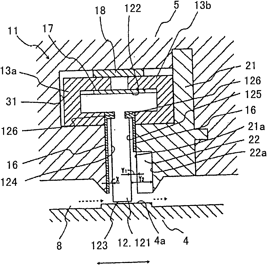
[0040] First, as the first embodiment, regarding a shaft seal mechanism composed of a sheet seal having one split portion (referred to as a split-type sheet seal) and a structure for attaching the shaft seal mechanism to a stator, refer to figure 1 Be explained.

[0041] figure 1 It shows a shaft seal mechanism composed of sheet seals and a structure in which the shaft seal mechanism is attached to a stator viewed...


PUM


Abstract

Provides a shaft seal mechanism for improving air pressure distribution near the split portion of the sheet seal, improved sealing performance, a structure for mounting the shaft seal mechanism on the stator, and a turbine, and the structure for mounting the shaft seal mechanism on the stator is provided on the A structure in which an annular space between the rotor and the stator and an annular shaft seal mechanism having one or more divided parts are attached to the stator, wherein the shaft seal mechanism is composed of a laminated sheet group consisting of a plurality of sheets, and the sheet group is connected to the rotor. Sliding contact, and the outer peripheral root of the thin plate group is bonded, the inner peripheral free end is not bonded, the rotor surface forms an acute angle with the thin plate, the above-mentioned annular space is divided into a high-pressure side area and a low-pressure side area, and the stator can accommodate The groove of the above-mentioned shaft seal mechanism is inserted into the gap formed after the above-mentioned shaft seal mechanism is assembled into the above-mentioned groove to install the shaft seal mechanism on the stator. An annular recess is arranged on the surface.

Description

technical field [0001] The present invention relates to a shaft seal mechanism used in a turbine, a structure for attaching the shaft seal mechanism to a stator, and a turbine equipped with them. Background technique [0002] Generally, a turbine includes stationary blades and moving blades surrounding the rotor, and includes a shaft seal mechanism surrounding the rotor in order to reduce the leakage of working fluid flowing from the high-pressure side to the low-pressure side. As an example of such a shaft seal mechanism, there are sheet seals shown in JP-A-2002-13647, JP-A-2003-113945, and the like. [0003] Turbines include gas turbines and steam turbines, and as an example, the overall structure of a turbine is as follows Figure 8 shown. The air compressed in the compressor 1 is mixed with fuel and combusted in the combustor 2 . The combustion gas generated in the burner 2 as the working fluid expands, and in the process of passing through the stationary blades 6 and ...

Claims


Application Information

Patent Timeline
Patent Type & Authority Patents(China)
IPC IPC(8): F16J15/44F01D11/02F02C7/28F16J15/22F16J15/3272F16J15/54
CPCF16J15/3292
Inventor 西本慎筱原种广上原秀和中野隆
Owner MITSUBISHI HEAVY IND LTD
Why Eureka
Try Eureka