
Grinding machine and method for grinding a workpiece

A grinding machine and grinding technology, which is applied to machine tools, grinders, abrasive belt grinders and other directions suitable for grinding workpiece planes, and can solve the problems of long response time and disadvantage.

Inactive Publication Date: 2009-11-11
于尔根・黑泽曼
View PDF10 Cites 0 Cited by
  • Summary
  • Abstract
  • Description
  • Claims
  • Application Information

AI Technical Summary

Problems solved by technology

The pneumatically driven pressure beam is controlled by means of solenoid valves, which disadvantageously have a relatively long response time

Method used


Image

  • Grinding machine and method for grinding a workpiece
  • Grinding machine and method for grinding a workpiece
  • Grinding machine and method for grinding a workpiece

Examples


Embodiment Construction

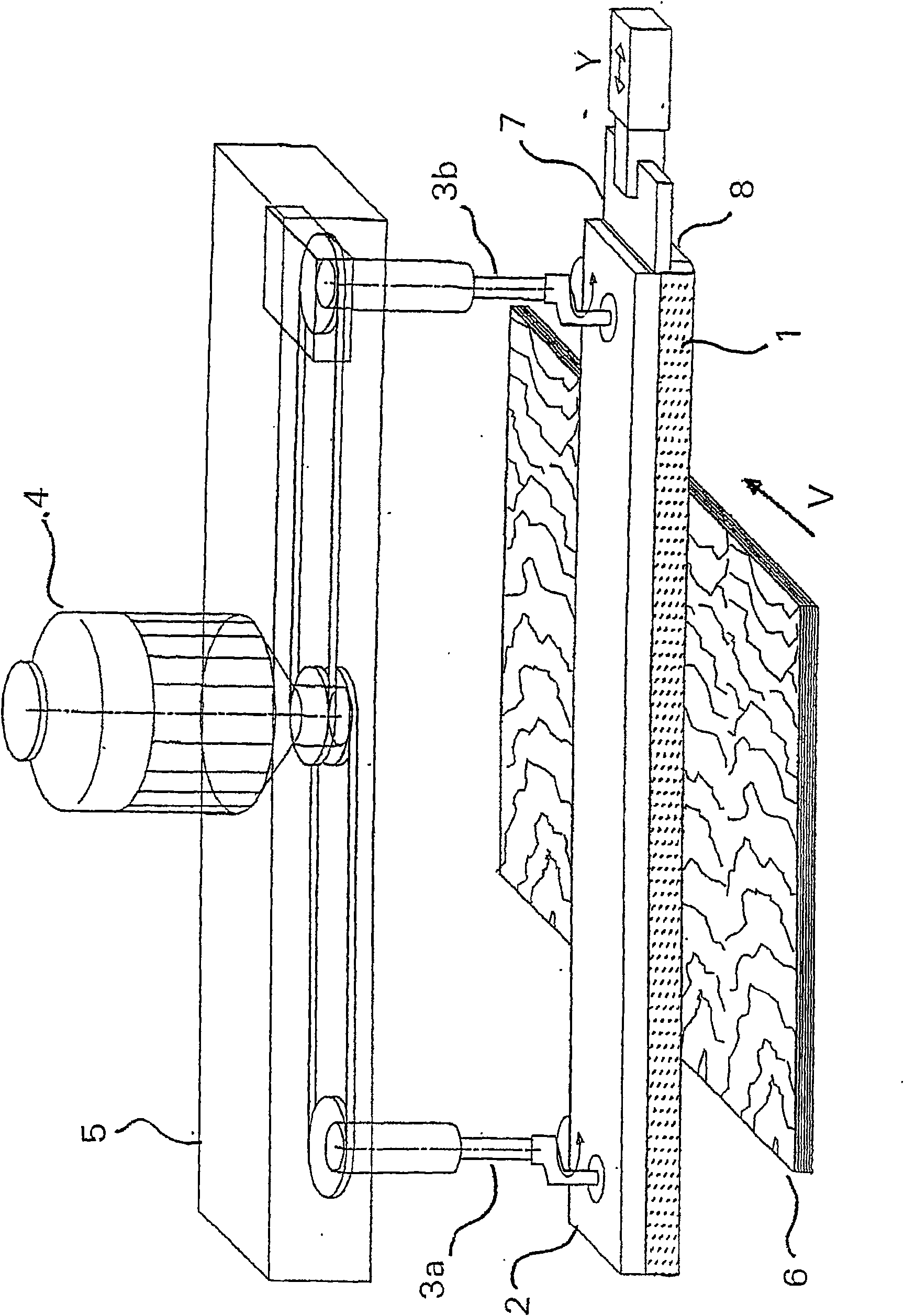
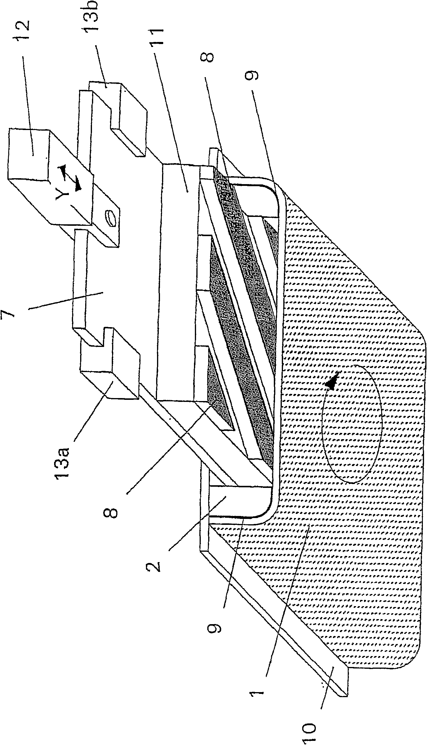
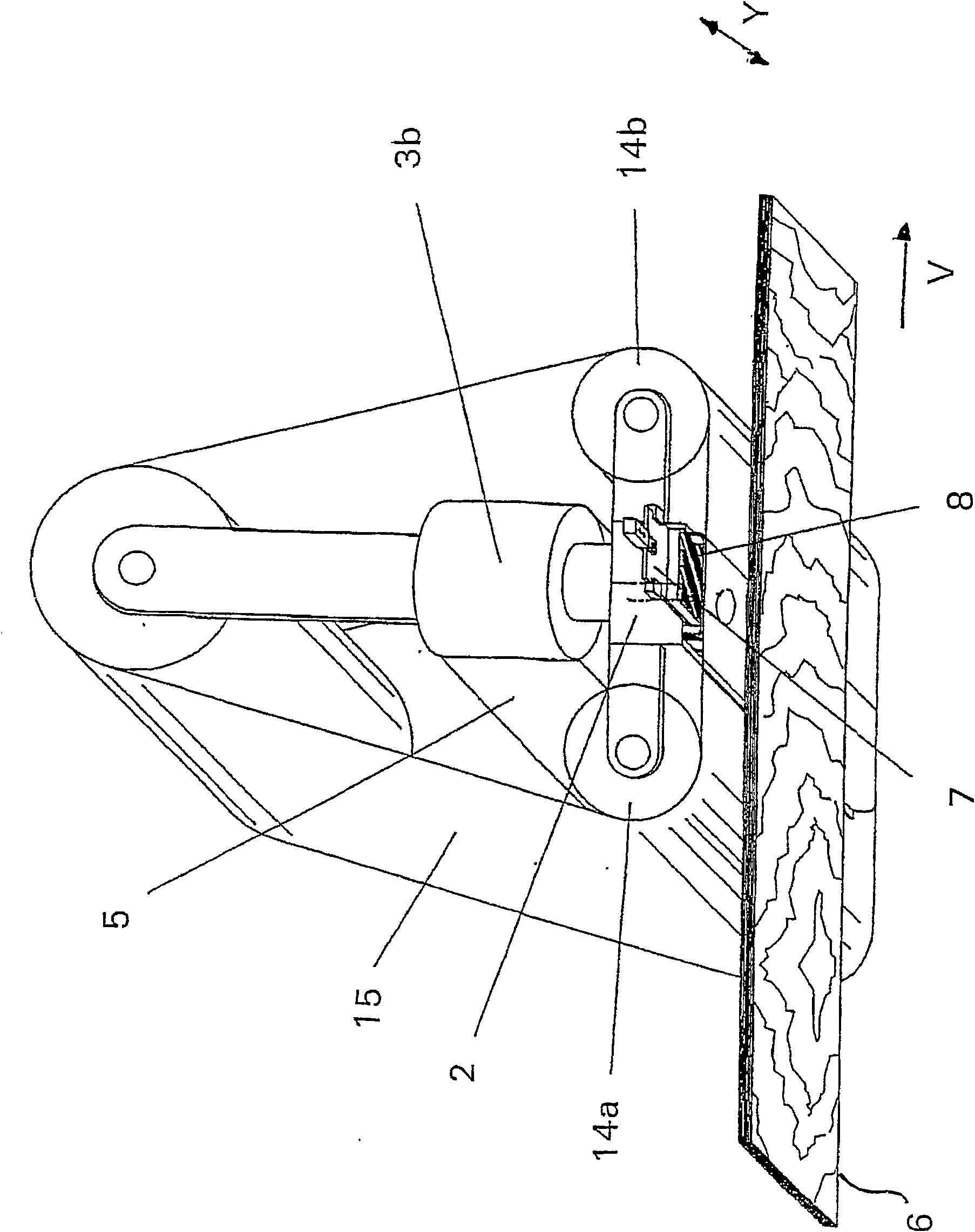
[0029] figure 1 A grinding machine according to the invention can be seen in a view in a cross-section perpendicular to the feed direction V. An abrasive element 1 in the form of an abrasive cloth or abrasive belt is mounted exchangeably on a holding device 2 . The holding device 2 itself is carried by at least one eccentric shaft 3 perpendicular to the grinding plane, ie perpendicular to the grinding surface of the abrasive element 1 , which can be driven in rotation by an electric motor 4 at a variable rotational speed. The abrasive material 1 is forced to perform a circular grinding movement in the grinding plane by the eccentric shaft 3 . The electric motor 4 itself is fixedly connected to a grinder frame 5 . The supporting device of at least one of the provided eccentric shafts 3 can move in one direction of the grinding plane, preferably in the Y direction perpendicular to the feed direction V, so as to compensate for the longitudinal expansion of the grinding machine ...


PUM


Abstract

Disclosed is a grinding machine comprising oscillating driving means ( 3, 4 ) for setting grinding means ( 1 ) into an oscillating grinding motion and an actuation device ( 7 ) that is provided with a plurality of actuation areas ( 8 ) which can be triggered such that different zones of the grinding means ( 1 ) are alternately actuated independently of the oscillating grinding motion.

Description

technical field [0001] The invention relates to a grinding machine with an oscillating drive for setting an abrasive element into an oscillating grinding motion. The invention also relates to a method for grinding a workpiece with such a grinding machine by means of an oscillating grinding movement. Background technique [0002] Such a grinding machine is described, for example, in the embodiment of a belt grinding machine in EP 0 543 947 B1. The abrasive elements attached to a plate and the vibration drive are coupled to the grinder frame in such a way that a second movement of the plate relative to the grinder frame is superimposed on the translational orbital movement. The formation of regular grinding patterns should be avoided by the two superimposed movements. These two superimposed movements are coupled to each other. [0003] For example, EP 0 155 380 B1 discloses a belt grinding machine having a multi-section pressure bar with a plurality of pressure shoes arrang...

Claims


Application Information

Patent Timeline
Patent Type & Authority Patents(China)
IPC IPC(8): B24B7/28B24B7/02
CPCB24B21/22B24B7/02B24B7/28
Inventor 于尔根·黑泽曼
Owner 于尔根・黑泽曼
Learn More