
Electroforming thin blade grinding wheel

A technology of thin blades and grinding wheels, applied in the direction of abrasives, bonded grinding wheels, metal processing equipment, etc., can solve the problems of inability to cut off, low concentration of abrasive grains, peeling, etc., to achieve wear resistance, prolong the life of grinding wheels, and good The effect of sharpness

Inactive Publication Date: 2014-09-10
TOKYO SEIMITSU
View PDF5 Cites 1 Cited by
  • Summary
  • Abstract
  • Description
  • Claims
  • Application Information

AI Technical Summary

Problems solved by technology

[0005] However, in such a three-layer electroformed thin-edged grinding wheel composed of a central electroformed abrasive grain layer and outer electroformed abrasive grain layers on both sides described in such Patent Document 1, in the cutting of electronic material components as described above, If the central electroformed abrasive grain layer wears and forms an annular recess, the pair of outer electroformed abrasive grain layers on both sides will cut in first to cut off the metal lead frame and metal electrodes in the molded resin intermittently, so if For example, when cutting, the pair of outer electroformed abrasive grain layers does not contact with the lead frame and the electrode at the same time and cuts in. The resistance and load acting on the two outer electroformed abrasive grain layers become uneven, and the thin-edged grinding wheel may be cut. Vibration occurs in the layer thickness direction of the abrasive grain layer and swings
Also, if the thin-edged grinding wheel swings during cutting in this way, the cutting width of the grinding wheel must be set larger, so the number of electronic material parts that can be manufactured from a limited-sized substrate or the like decreases, and cutting itself may not be possible in some cases.
[0006] In addition, since the annular recess formed by the wear of the central electroformed abrasive layer takes in and removes the chips generated by the electroformed abrasive layers on both outer sides through one recess as described above, there must be a certain degree of difficulty. The width and depth are concave, and the problem that interlayer delamination tends to occur from the boundary between the central electroformed abrasive grain layer and the outer electroformed abrasive grain layer that are thus greatly depressed
Furthermore, since the concentration of the abrasive grains is low, the central electroformed abrasive grain layer that is easily worn is arranged with a large width and depth, so there is a lack of wear resistance as a whole of the electroformed thin-edged grinding wheel, and the life expectancy is relatively short. reach problem

Method used


Image

  • Electroforming thin blade grinding wheel
  • Electroforming thin blade grinding wheel
  • Electroforming thin blade grinding wheel

Examples


Embodiment

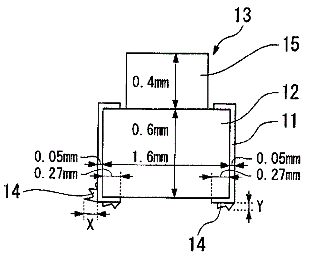
[0037]Next, more specific examples will be given to describe the effects of the present invention. In this example, by using the electroformed thin-edged grinding wheel based on the above-mentioned embodiment, image 3 Cutting of the LED workpiece 13 composed of a glass epoxy resin substrate 12 having metal (Cu) electrodes 11 as shown, measured the size of the burr 14 generated from the electrode 11 at the initial stage of cutting and at the time of 50m cutting (wherein, Such as image 3 As shown, X is the size of the burrs 14 extending in the lateral direction (feed direction), and Y is the size of the burrs 14 extending in the downward direction. ). The results are referred to as Example 1, and are shown in Table 1 together with the abrasive grain content in the first to fifth abrasive grain layers of the thin-edged abrasive grain layer. In addition, the reference numeral 15 part of the LED workpiece 13 is made of epoxy resin.

[0038] Among them, in this embodiment 1, t...


PUM


Abstract

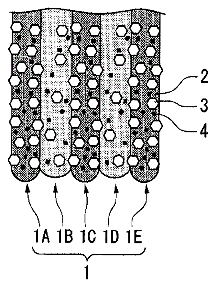
The present invention provides an electroformed thin edge grinding wheel for use in cutting an electronic material part such as a QFN (quad flat non-leaded package), an optical transmission module (IrDA) or an LED work, not only restraining the generation of burr, but also having high linearity to achieve high-accuracy cutting, further superior in wear resistance and peeling resistance to attain a long life of a grinding wheel and stably maintain a high grade to the cut electronic material part. This electroformed thin edge grinding wheel includes a thin edge abrasive layer 1 formed by dispersing abrasive grains 3 in a metal plated phase 2, wherein the thin edge abrasive grain layer 1 has first to fifth abrasive grain layers 1A to 1E sequentially stacked in the direction of a layer thickness. Among these, the content of abrasive grains 3 in the first, third and fifth abrasive grain layers 1A, 1C, 1E is set larger than that of abrasive grains 3 in the second and fourth abrasive grain layers 1B, 1D.

Description

technical field [0001] In particular, the present invention relates to an electroformed thin-edged grinding wheel suitable for use in cutting after die casting when electronic material parts are manufactured by mounting components and the like together on a substrate, cutting and singulating after die casting. Background technique [0002] For cutting during the production of such electronic material components, electroformed thin grinding wheels comprising an extremely thin abrasive grain layer in which superabrasive grains such as diamond are dispersed in a metal plating phase such as nickel have conventionally been used. However, in recent years, as such an electronic material component, for example, a component called QFN (quad flat non-leaded package) is obtained by mounting multiple components together on a lead frame, Electronic material components that are molded together and then cut into pieces, manufactured, or optical transmission modules of the IrDA (Infrared Da...

Claims


Application Information

Patent Timeline
Patent Type & Authority Applications(China)
IPC IPC(8): B24D5/12
CPCB24D3/06B24D5/12B24D5/14
Inventor 池田吉隆花见隆之佐藤英格
Owner TOKYO SEIMITSU
Learn More