A 3D printing closed impeller abrasive flow finishing device

A closed impeller and processing device technology, which is applied in metal processing equipment, grinding workpiece support, grinding/polishing equipment, etc., can solve the problems of low production efficiency, harsh working environment, and poor consistency of processing quality, so as to prevent downturn Round, to avoid the effect of uneven processing

Active Publication Date: 2020-05-08
XIAN SPACE ENGINE CO LTD
View PDF6 Cites 0 Cited by
  • Summary
  • Abstract
  • Description
  • Claims
  • Application Information

AI Technical Summary

Problems solved by technology

[0003] 3D printing is an emerging technical field of overall parts and rapid prototyping. The surface quality of the formed metal parts cannot meet the requirements for direct use.
At present, the surface finishing methods of parts are mainly manual grinding, sand blowing and shot blasting, which are not only labor-intensive, the working environment is harsh, but also the production efficiency is low and the consistency of processing quality is poor.
[0004] The inner cavity of the closed impeller has a three-dimensional twisted blade structure, with six long and short blades, and the blades are curved with variable curvature in the radial and axial directions. In addition, the space between the impeller blades and the flow channel is small, and cannot be entered by manual grinding. , Shot blasting cannot achieve uniform finishing of complex free-form surfaces inside the product

Method used


Image

  • A 3D printing closed impeller abrasive flow finishing device
  • A 3D printing closed impeller abrasive flow finishing device
  • A 3D printing closed impeller abrasive flow finishing device

Examples


Embodiment

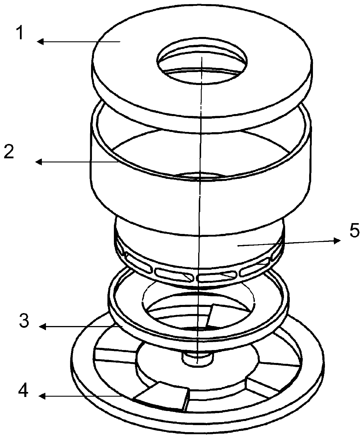
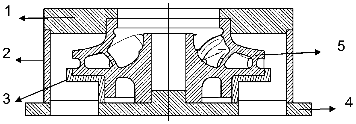
[0024] The center of the lower deflector 4 is provided with a Ф28 boss, and four 60° fan-shaped channels are arranged around it; the inner ring 3 is an L-shaped rotary body, which cooperates with the lower cover of the closed impeller part, and the entire lower cover of the closed impeller The plate is "wrapped", the upper edge is flush with the top of the impeller lower cover, and the width is 5mm, which is equivalent to extending the outline of the lower cover by 5mm in the radial direction, and transferring the rounding effect to the inner ring during abrasive flow processing upper edge.

[0025] The inner ring 3 and the closed impeller are placed at the center of the lower deflector 4. The outline size of the lower deflector 4 is Φ230mm. It is placed on the lower abrasive cylinder of the abrasive flow equipment. The boss of the lower deflector 4 and the center of the closed impeller The through hole is used to fix the parts and prevent the radial displacement of the parts ...


PUM


Abstract

The invention discloses a 3D printing closed impeller abrasive flow finishing device, which comprises an upper deflector, a protective sleeve, an inner ring, a lower deflector and a closed impeller. There are several raised fan-shaped channels on the outside of the table, the inner ring is L-shaped rotary body, placed on the inner edge of the raised fan-shaped channel, the protective cover is a hollow rotary structure, placed on the outer edge of the raised fan-shaped channel, and the upper guide The flow plate is placed on the protective cover, and a stepped hole is opened in the center of the closed impeller. The through hole under the closed impeller matches the boss of the lower deflector, the lower edge of the closed impeller cooperates with the lower deflector, and the closed impeller lower The cover plate and the inner ring cooperate with each other, the upper abrasive channel of the closed impeller cooperates with the step hole of the upper deflector, the pistons of the upper abrasive cylinder and the lower abrasive cylinder reciprocate synchronously up and down, and push the abrasive to flow between the blades of the closed impeller and between the blades. for abrasive flow machining.

Description

technical field [0001] The invention relates to a 3D printing closed impeller abrasive flow finishing device, which is used for finishing the surfaces of closed impeller blades and flow channels, and belongs to the field of surface finishing of 3D printing metal parts. Background technique [0002] The closed impeller is a key part of the liquid rocket engine turbo pump, and its surface quality directly affects the head and efficiency of the turbo pump. The reduction of the surface roughness of the inner cavity flow channel helps to increase the head of the turbo pump and reduce the pressure of the turbo pump. Speed, improve the reliability of the engine work. [0003] 3D printing is an emerging technical field of overall parts and rapid prototyping, and the surface quality of formed metal parts cannot meet the requirements for direct use. At present, the surface finishing methods of parts are mainly manual grinding, sand blowing and shot blasting, which are not only labor-...

Claims


Application Information

Patent Timeline
Patent Type & Authority Patents(China)
IPC IPC(8): B24B31/116B24B41/06
CPCB24B31/116B24B41/06
Inventor 李护林杨欢庆陈振宇王琳彭东剑周亚雄王云
Owner XIAN SPACE ENGINE CO LTD
Why Eureka
Try Eureka