Fluorescent material coating apparatus and method of coating fluorescent substance using the same

A technology of fluorescent substances and coating devices, which is applied in the application of luminous paints, tube/lamp screen manufacturing, building construction, etc. It can solve the problems of complex operation process, long time required for inserting and taking out glass tubes, and glass tube Problems such as large temperature difference to achieve the effect of ensuring the uniformity of the coating

Inactive Publication Date: 2009-11-11
WEIHAI DMS OPTICAL ELECTROMECHANICAL CO LTD
View PDF4 Cites 2 Cited by
  • Summary
  • Abstract
  • Description
  • Claims
  • Application Information

AI Technical Summary

Problems solved by technology

[0010] However, the above-mentioned rotary coating method can only install a small amount of glass tubes on a disk-shaped stage with limited size, that is, 3-5 glass tubes, and complete the coating through processes such as coating fluorescent liquid and drying. process
Therefore, not only is it difficult to mass-produce fluorescent lamps, but it is also necessary for the operator to load the glass tubes into the stage one by one and remove the glass tubes one by one after the coating is completed.
Therefore, not only the operation process is complicated, but also there are problems such as the time required for inserting and taking out the glass tube is too long.
[0011] In particular, since after the inner surface of the glass tube is coated with fluorescent liquid, only hot air is supplied to the inside of the glass tube when drying the coating, which results in a large temperature difference between the inner and outer surfaces of each glass tube.

Method used


Image

  • Fluorescent material coating apparatus and method of coating fluorescent substance using the same
  • Fluorescent material coating apparatus and method of coating fluorescent substance using the same
  • Fluorescent material coating apparatus and method of coating fluorescent substance using the same

Examples


Embodiment Construction

[0034] The present invention will be described in more detail below in conjunction with the accompanying drawings and embodiments.

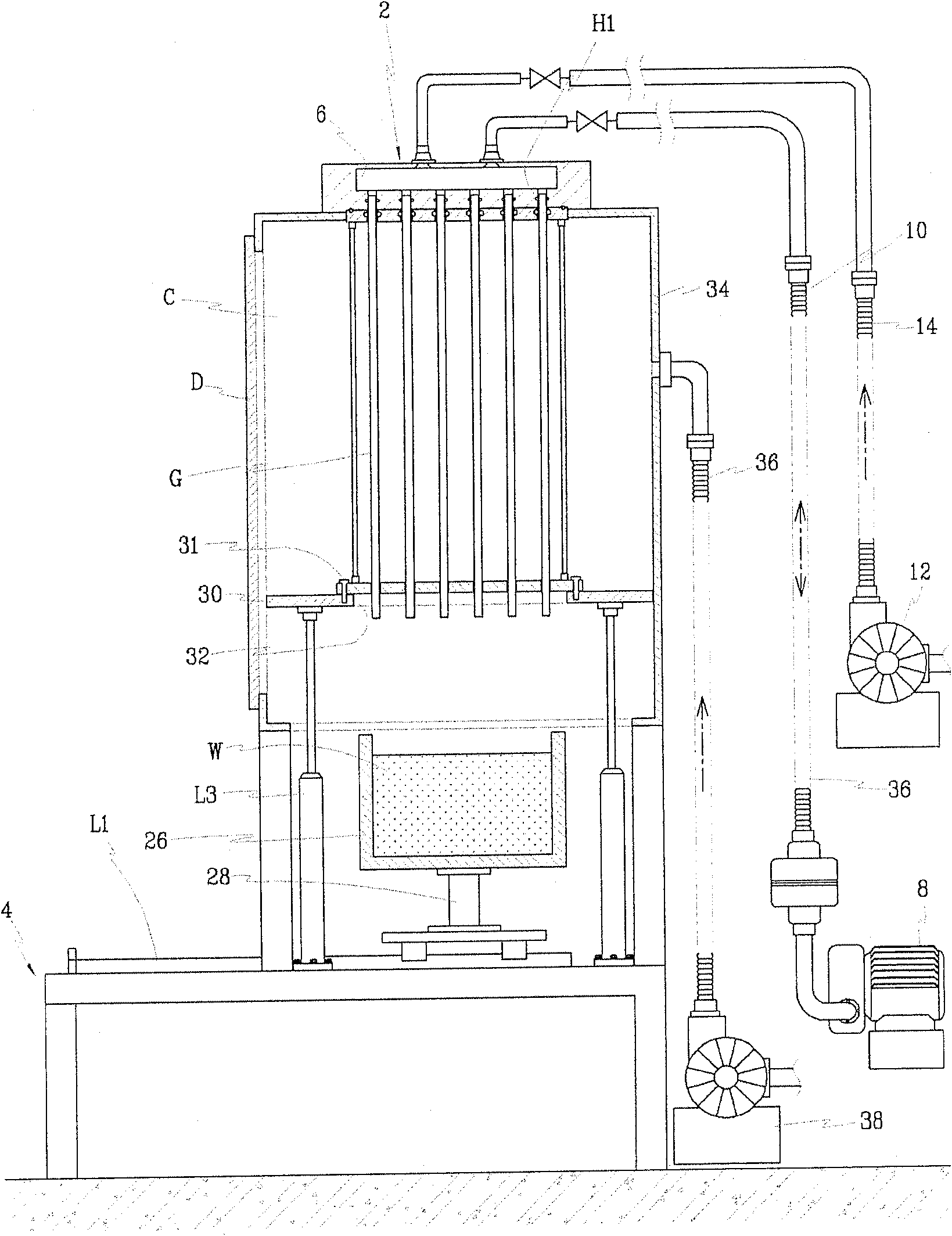
[0035] figure 1 It is a structural schematic diagram of a fluorescent substance coating device for manufacturing fluorescent lamps according to the present invention, and the number 2 in the figure represents a distributing device. The distribution device 2 is fixed on the upper part of the bracket 4 , and the distribution device 2 is provided with a distribution chamber 6 .

[0036] The distribution chamber 6 communicates with the vacuum pump 8 through a flexible hose (flexible hose) 10, so that a negative pressure can be generated in the distribution chamber 6, and the distribution chamber 6 is connected with a heating device through a flexible hose 14. A first blower 12 of a device (not shown) is connected to draw hot air.

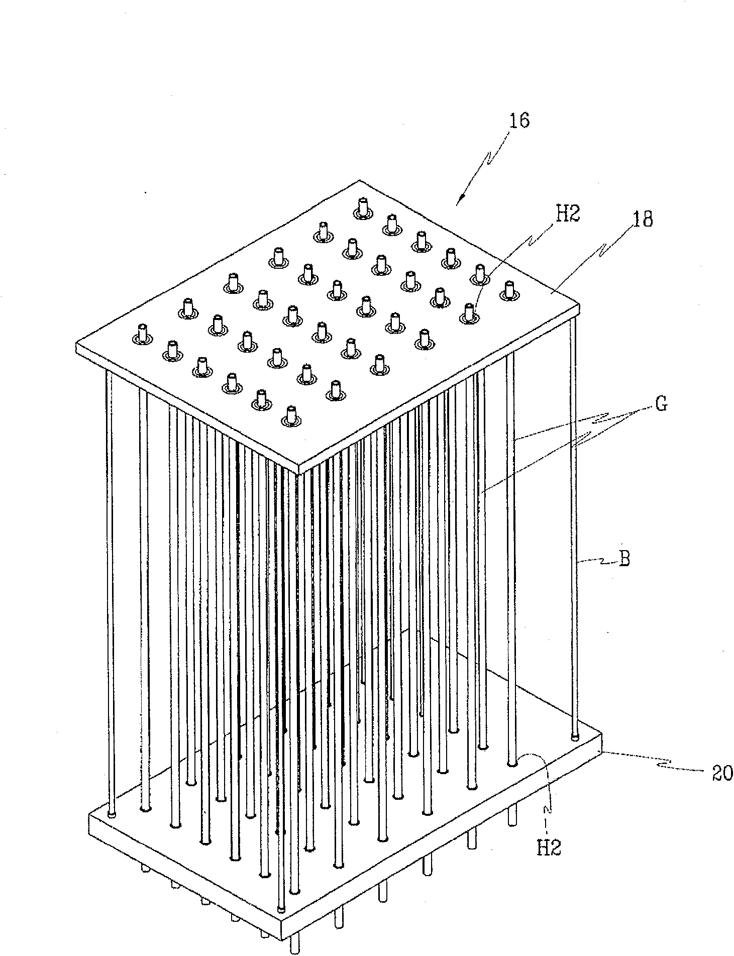
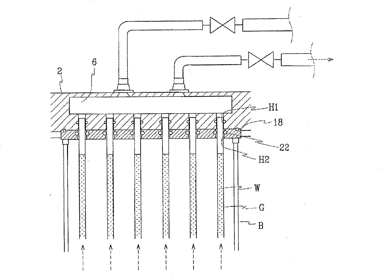
[0037] The distribution chamber 6 is perforated with at least two communication holes H1, the communication holes H1 a...


PUM


Abstract

The invention discloses a fluorescent substance coating device for manufacturing fluorescent lamps and a coating method using the device, which comprises: a loading box for arranging a plurality of glass tubes in parallel; The distributing device of the distribution chamber provided; the fluorescent substance storage tank arranged under the plurality of glass tubes; used to lift the loading box or storage tank so that one end of the plurality of glass tubes arranged on the loading box A mobile device that can be in contact with the fluorescent substance; a negative pressure generating device that generates negative pressure inside the universal chamber so that the fluorescent substance is sucked into the glass tube; An air supply device for drying that supplies hot gas for drying so that the gas flows into the inside of the glass tube to dry the fluorescent material. Through the present invention, fluorescent liquid can be coated on the inside of a plurality of glass tubes at the same time, conveniently and quickly, and the coating of fluorescent liquid can be evenly dried.

Description

technical field [0001] The present invention relates to a fluorescent substance coating device for manufacturing fluorescent lamps and a coating method using the device, in particular to a method for simultaneously coating fluorescent liquid on the inner surfaces of at least two glass tubes for fluorescent lamps in a simple and quick manner, and can A fluorescent material coating device and a coating method thereof for drying coated fluorescent liquid at a uniform drying temperature. Background technique [0002] In general, fluorescent lamps are broadly classified into cold cathode fluorescent lamps (CCFL: Cold Cathode Fluorescent Lamp) and external electrode fluorescent lamps (EEFL: External Electrode Fluorescent Lamp). Compared with the cold cathode fluorescent lamp, the external electrode fluorescent lamp has the characteristics of good luminous quality, long lamp life and low cost of use, and can be made into a pocket-sized structure, so it is often used as the backligh...

Claims


Application Information

Patent Timeline
Patent Type & Authority Patents(China)
IPC IPC(8): H01J9/22
CPCE04G25/061
Inventor 李永哲金东吉金圣中金全九赵弘来
Owner WEIHAI DMS OPTICAL ELECTROMECHANICAL CO LTD
Why Eureka
Try Eureka