Picture processing engine and picture processing system including the picture processing engine

一种图像处理、引擎的技术,应用在图像数据处理、图像数据处理、具有多个处理单元的架构等方向,能够解决面积成本大、功耗大、功耗增大等问题

Inactive Publication Date: 2009-11-25
RENESAS ELECTRONICS CORP
View PDF7 Cites 0 Cited by
  • Summary
  • Abstract
  • Description
  • Claims
  • Application Information

AI Technical Summary

Problems solved by technology

According to this method, as the number of computing units operating in parallel increases, the number of instructions read in one cycle also increases, resulting in large power consumption.
In addition, the number of register ports increases in direct proportion to the number of arithmetic units, and the area cost is very high, which also increases power consumption

Method used


Image

  • Picture processing engine and picture processing system including the picture processing engine
  • Picture processing engine and picture processing system including the picture processing engine
  • Picture processing engine and picture processing system including the picture processing engine

Examples


Embodiment 1

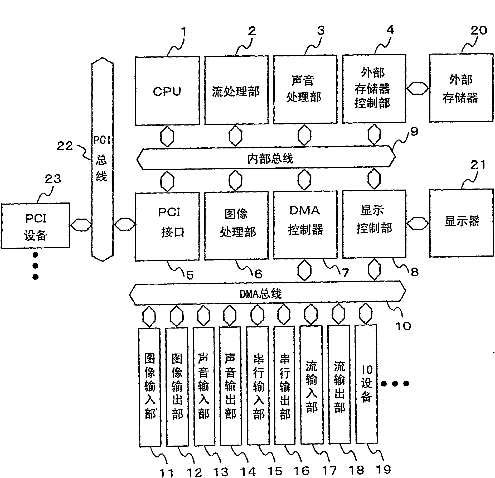
[0051] A first embodiment of the present invention will be described in detail with reference to the drawings. figure 1 is a block diagram of the embedded system of this embodiment. This embedded system interconnects the following parts on the internal bus 9: CPU1, which carries out system control and general processing; stream processing part 2, which carries out 1 processing of image codecs such as MPEG, i.e. stream processing; image processing part 6. Cooperate with the stream processing unit 2 to encode and decode the image codec; the audio processing unit 3 performs encoding and decoding of audio codecs such as AAC or MP-3; The access of the constituted external memory 20; the PCI interface 5 is used to be connected to the standard bus, that is, the PCI bus 22; the display control part 8 controls image display; and the DMA controller 7 performs direct memory access to various IO devices.

[0052] Various I / O devices are connected to the DMA controller 7 via the DMA bus 1...

Embodiment 2

[0151] use Figure 14 A second embodiment of the present invention will be described. Figure 14 It is a block diagram of the image processing unit 66 of this embodiment. compared to Image 6 The image processing engine 66 of the first embodiment shown has three differences. The first point is that the input data 30i and the calculation data 30wb of the CPU unit 30 are connected to the vector calculation unit 46 . The input data 30i is data to be input to the register file 304 in the CPU unit 30, and the data of the register file 304 can be updated. The calculation data 30wb is a calculation result of the CPU unit 30 and is input to the vector calculation unit 46 . The second place is to replace Image 6 The command memory control unit 32 is connected to the command memory control unit 47 . The instruction memory control unit 47 has a plurality of program counters and controls the instruction memory 31 . Furthermore, the third difference is that the vector calculation u...

Embodiment 3

[0171] use Figure 20 The third embodiment will be described. Figure 20 is a configuration diagram of the CPU section arranged in the image processing engine 66 of the present embodiment. In the first embodiment, it is composed of one CPU unit 30 ; in the second embodiment, it is described that it is composed of two CPUs, namely, the CPU unit 30 and the vector operation unit 46 . In the third embodiment, two or more CPUs are connected in series or in a ring. exist image 3 Among them, the CPU unit 30 that can access the data memory 35 is arranged on the first CPU, and a plurality of vector calculation units 46 and 46n are connected in series, and the CPU unit 30s that can access the data memory 35 is connected to the end. The calculation data 30i of the CPU unit 30s is again connected to the input data unit of the CPU unit 30 . At this time, each CPU has a program counter structure, and actually has a plurality of Figure 16 The structure of the program counter in the in...


PUM


Abstract

The present invention provides a power reduction technique in the case of using a processor for image processing. For this purpose, for example, an operand of an instruction is provided with a portion specifying a two-dimensional source register and a destination register, and a unit is provided that performs operations using a plurality of source registers in a plurality of cycles to obtain a plurality of destinations. Also, in an instruction that takes multiple cycles to obtain a destination using multiple source registers, a data rounding operator is connected to the last stage of the pipeline. With these configurations, for example, by reducing the number of times of accessing the instruction memory, the power consumed when reading the instruction memory is reduced.

Description

[0001] This application claims priority from Japanese application JP2006-170382 filed on June 20, 2006, the contents of which are hereby incorporated by reference in this application. technical field [0002] The technical field relates to an image processing engine and an image processing system including the image processing engine, in particular to an image processing engine connecting a CPU and a direct memory access controller with a bus and an image processing system including the image processing engine. Background technique [0003] With the miniaturization of the semiconductor process, technologies such as SOC (System on Chip) that realizes a large-scale system on one LSI or SIP (System in Package) that mounts multiple LSIs in one package have become mainstream. By scaling up this logic, as seen in embedded applications, it is possible to install completely different functions such as a CPU core, an image codec accelerator, or a large-scale DMAC module in one LSI. ...

Claims


Application Information

Patent Timeline
Patent Type & Authority Patents(China)
IPC IPC(8): G06T1/20G06F15/80
CPCG06F9/30014G06F9/3885G06F9/30036G06F9/30087G06F15/16G06F15/76G06T1/00
Inventor 细木浩二江浜真和中田启明岩田宪一望月诚二汤浅隆史小林幸史柴山哲也植田浩司升正树
Owner RENESAS ELECTRONICS CORP
Why Eureka
Try Eureka