
Cooling plate

一种冷却板、冷却剂的技术,应用在冷却装置、炉子冷却装置、炉冷等方向,能够解决铜的焊接技术昂贵、高故障风险、费用高等问题,达到提高疲劳寿命的效果

Active Publication Date: 2009-12-02
KME SPECIAL PROD & SOLUTIONS GMBH
View PDF7 Cites 0 Cited by
  • Summary
  • Abstract
  • Description
  • Claims
  • Application Information

AI Technical Summary

Problems solved by technology

Soldering of copper is technically very expensive and has a high risk of failure
[0004] In the known case, a further problem is that the inspection of fillet welds, especially for example in the case of brazed welds by means of color flaw detection, is technically possible but expensive

Method used


Image

  • Cooling plate
  • Cooling plate
  • Cooling plate

Examples


Embodiment Construction

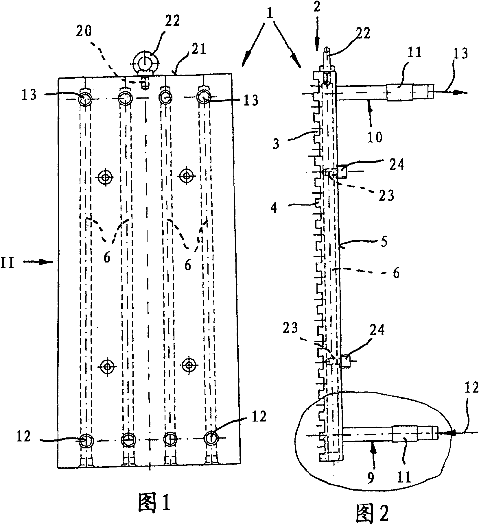
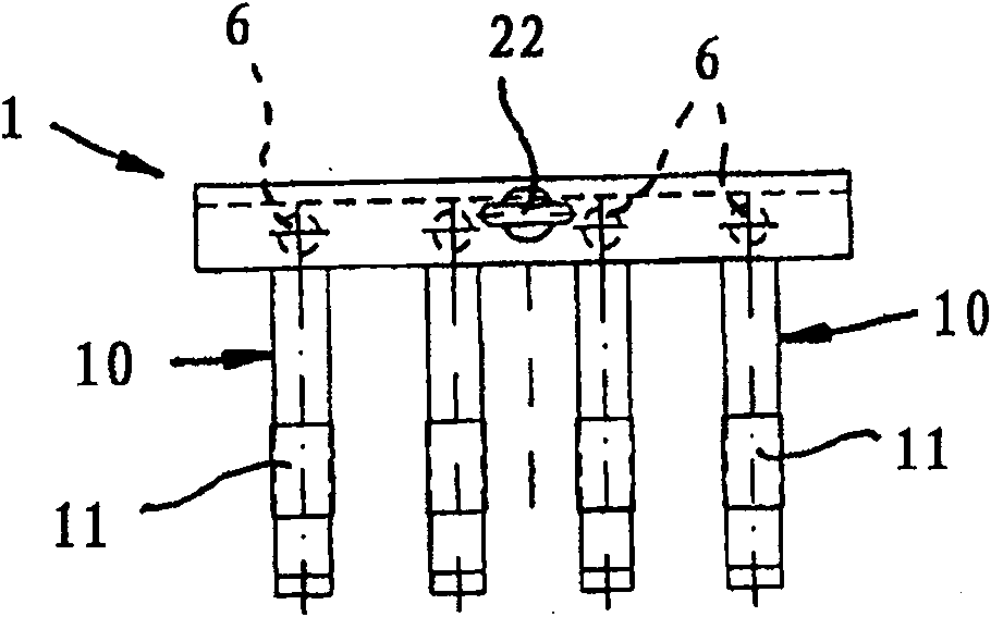
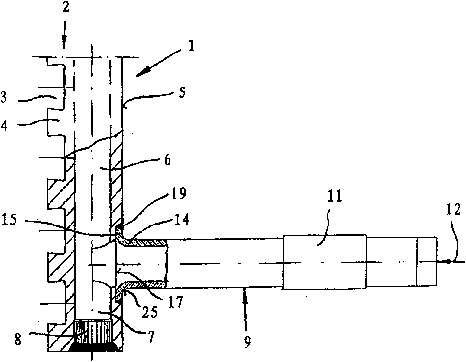
[0026] exist Figures 1 to 5 A cooling plate made of copper or a copper alloy for a well-type furnace is indicated by the numeral 1 in it. The cooling plate 1 alternately has grooves 3 and projections 4 on the hot side 2 of the plate. The cooling plate 1 has a planar design on the plate cold side 5 .

[0027] A plurality of bores 6 forming deep bores for receiving a coolant, such as water in particular, are provided on the cooling plate 1 . The bores 6 designed as blind bores have a plug 8 at the inlet end 7 .

[0028] The bores 6 can be connected individually or also in groups (with a correspondingly reduced diameter) to connecting pipes 9 , 10 . exist Figures 1 to 5 Among them, each hole is connected with a connecting pipe 9, 10, leading to coolant. However, it is also conceivable that the holes 6 of smaller diameter are combined in groups (two to four holes 6) in the region of the connecting pipes 9, 10, and then these holes 6 are connected to the connecting pipes via...


PUM


Abstract

The invention relates to a cooling plate (1) made of copper or a copper alloy for a pit furnace, which has holes (6) for accommodating a coolant. The holes (6) are connected to a coolant inlet (12) and a coolant outlet via connecting pipes (9) welded to the cold plate side (5). At its plate-side end (14), the connecting pipe (9) is provided with a bead (15) formed by a bead. The flange (15) is inserted into the groove (17) of the cold plate side (5) and is welded to the cold plate side (5) on the circumference by a V-shaped weld seam (19).

Description

technical field [0001] The invention relates to a cooling plate for a pit furnace made of copper or a copper alloy. Background technique [0002] A cooling plate of this type is known from EP 0 951 371 B1. Holes are provided in the cooling plate for accommodating a coolant, in particular water, which are connected to a coolant inlet and a coolant outlet via connecting pipes welded on the cold side of the plate. The inner cross-section of the connecting pipe is usually adapted to the diameter of these holes. The connection tubes are usually fixed to the cooling plate in such a way that some shallow grooves are made on the cold side of the plate to match the outside diameter of the connection tubes, and the ends of the connection tubes on the cooling plate side are inserted into these grooves Inside, the connecting pipe is then welded to the cooling plate via a fillet weld. The plate-side end of the connecting pipe is not specially treated here. In most cases they are cham...

Claims


Application Information

Patent Timeline
Patent Type & Authority Patents(China)
IPC IPC(8): F27B1/24B22D11/00
CPCF27D2009/0048C21B7/10F27D9/00F27D2009/0062F27D1/12E02D17/205E02D2600/20E02D2200/165
Inventor 克里斯托弗·德拉特纳弗朗茨·凯泽赖因哈德·欣特曼弗兰克·伯埃尔特汉斯-京特·沃布克
Owner KME SPECIAL PROD & SOLUTIONS GMBH
Learn More