
Speed limiter of elevator

A technology of elevator speed limiter and overrunning clutch, which is applied to clutches, one-way clutches, elevators, etc., can solve the problems of discontinuous speed capture of speed limiter action, discontinuous action, influence of speed limiter, etc., so as to achieve safe elevator operation. Reliable, solve discontinuity, stable effect of pulling force

Active Publication Date: 2009-12-30
宁波申菱机电科技股份有限公司
View PDF6 Cites 18 Cited by
  • Summary
  • Abstract
  • Description
  • Claims
  • Application Information

AI Technical Summary

Problems solved by technology

[0003] 1) The discontinuity of the action speed capture of the speed limiter: the structure adopts the ratchet wheel to index the circumference. Due to the delay of the indexing ratchet wheel, the discontinuity of the action is caused. Elevator braking time extended;
[0004] 2) Delay of electrical switch action: Since the electrical switch action is completed by hitting the plate of the electrical switch with the bolt on the centrifugal hammer, and it is a single-point trigger, that is, there can only be one time in a circle Motion capture, delaying the action of electrical switches;
[0005] 3) Instability of pulling force: Since the pulling force is directly participated by the speed governor sheave and completed after the wire rope is pressed by the rope pressing device, the sheave wheel groove in this mechanism will be damaged under the wear and tear of the rope pressing device. A sudden increase or decrease in the pulling force will cause the pulling force to be unstable, which will have an adverse effect on the speed limiter itself

Method used


Image

  • Speed limiter of elevator
  • Speed limiter of elevator
  • Speed limiter of elevator

Examples


Embodiment 1

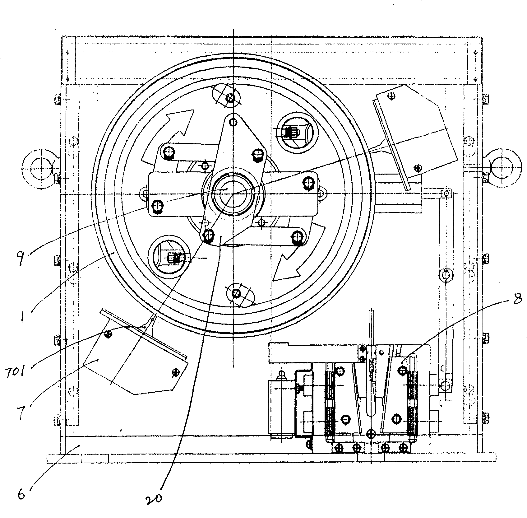
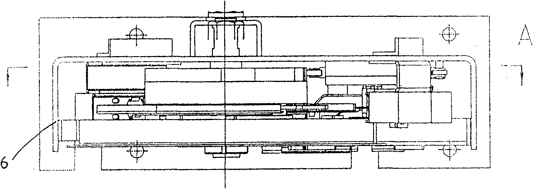
[0019] Depend on Figure 2-Figure 5 As shown, a kind of elevator overspeed governor of the present invention comprises frame 6, sheave 1, sheave shaft 9, overspeed switch 7, roller type overrunning clutch; Said sheave 1 is installed on frame by sheave shaft 9 6, the sheave 1 is equipped with a steel wire rope; said overspeed switch 7 is installed on the frame 6, and the overspeed switch 7 has a plate 701 that can contact with the roller type overrunning clutch. When the elevator overspeeds, the roller type overruns The clutch hits the beating plate of the overspeed switch under the action of centrifugal force to trigger the electrical switch action; the roller type overrunning clutch is composed of a group of inner and outer friction wheels 11, 10 and inner and outer friction wheels coaxially installed with the sheave. The friction pair composed of the friction roller 15 between the friction wheels and the centrifugal quadrilateral component group are composed; the said inner ...

Embodiment 2

[0022] In Embodiment 1, the outer friction wheel 10 and the frame 6 are fixed so that the outer friction wheel 10 is tightly fitted with the sheave shaft, and the rest of the embodiment 1 is repeated.

Embodiment 3

[0024] In embodiment 1, change the fixation of inner friction wheel 11 and sheave 1 to be that outer friction wheel 10 is fixed with sheave 1, and outer friction wheel is not fixed with frame 6; Fixed, all the other repeat embodiment 1.


PUM


Abstract

The invention relates to a novel elevator overspeed governor applicable to the protection of ascending overspeed or descending overspeed or bidirectional overspeed of the ascending and the descending. The elevator overspeed governor comprises a frame, a rope pulley, a rope pulley shaft, an overspeed switch and a roller-type overrunning clutch; wherein, the roller-type overrunning clutch consists of a set of internal friction pulley and external friction pulley coaxially arranged with the rope pulley, a friction roller between the internal friction pulley and the external friction pulley, and a centrifugal quadrilateral component; wherein, the centrifugal quadrilateral component consists of two centrifugal sheets, two balancing springs and two connecting rods. By adopting the roller-type overrunning clutch instead of the conventional centrifugal ratchet wheel typed clutch structure, the overspeed governor solves the discontinuity and the instability of the action of the overspeed governor and the delay of the action of an electrical switch, thereby enabling the elevator overspeed governor to act instantaneously when overspeed occurs, realizing the continuous speed capture of the overspeed governor, stabilizing the drawing force of the steel wire rope and the rope pulley and resulting in safer and more reliable operation of the elevator.

Description

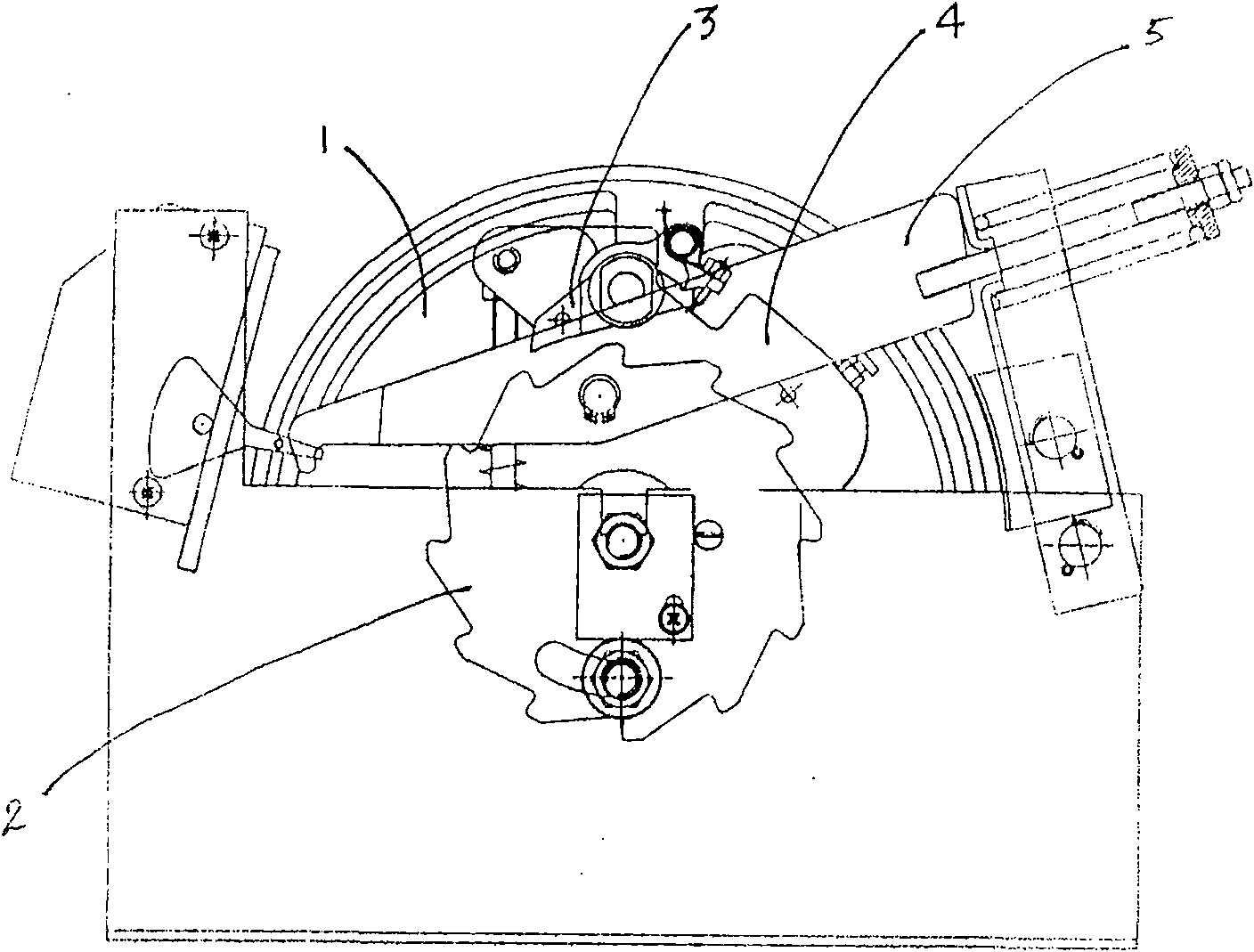
technical field [0001] The invention relates to the technical field of a safety device used for detection and correction of an elevator's upward overspeed, downlink overspeed or uplink and downlink bidirectional overspeed faults, in particular to an elevator speed limiting device. Background technique [0002] The currently used elevator overspeed protection devices all drive the elevator braking device to act through the speed limiter, so that the elevator decelerates and stops; existing elevator speed limiters such as figure 1 As shown, it adopts the centrifugal ratchet clutch structure, the wire rope passes through the rope wheel, the ratchet is installed outside the rope wheel, the pawl matched with the ratchet is hinged on the rope wheel, and the pawl is also connected with the centrifugal hammer; when the elevator overspeed, The centrifugal hammer of the elevator speed limiter moves under the action of centrifugal force, and the pawl blocks the ratchet to brake the rop...

Claims


Application Information

Patent Timeline
Patent Type & Authority Patents(China)
IPC IPC(8): B66B5/04F16D41/064
Inventor 左永民励海云
Owner 宁波申菱机电科技股份有限公司
Learn More