LED light projector image forming apparatus

An imaging device and LED lamp bead technology, which is applied in the field of optoelectronics, can solve problems such as damage, high temperature of other lamp beads, and short life

Inactive Publication Date: 2009-12-30
GUANGZHOU YAJIANG PHOTOELECTRIC EQUIP CO LTD
View PDF9 Cites 0 Cited by
  • Summary
  • Abstract
  • Description
  • Claims
  • Application Information

AI Technical Summary

Problems solved by technology

[0004] 2. Discharge bulbs also have some other technically unique disadvantages: 1) Short life (for example: the life of a 1200W bulb is about 1000 hours, and the life of a 250W bulb is about 3000 hours); 2) It cannot be changed from 100% to 0% Dimming smoothly; 3) When working at a relatively low wattage, the life of the bulb will be shortened (for example: the life of the bulb will be longer when working at 100% wattage than at 30% wattage); 4) Discharge bulbs are not easy to flicker; 5) Most discharge bulbs need warm-up time
[0006] In the light projection imaging device technology, there are also devices that use LEDs as light sources. Among them, LED (Light Emitting Diode), the English abbreviation of light-emitting diodes, however, the combination of multiple LED lamp beads used in the LED lighting equipment invented at present is shared. A heat sink installs all the LED lamp beads together, so that when any LED lamp bead overheats, the heat will increase the temperature of the entire heat sink, thereby reducing the heat dissipation function of the heat sink, and may even cause The temperature of other lamp beads is too high or even destroyed

Method used


Image

  • LED light projector image forming apparatus
  • LED light projector image forming apparatus
  • LED light projector image forming apparatus

Examples


Embodiment Construction

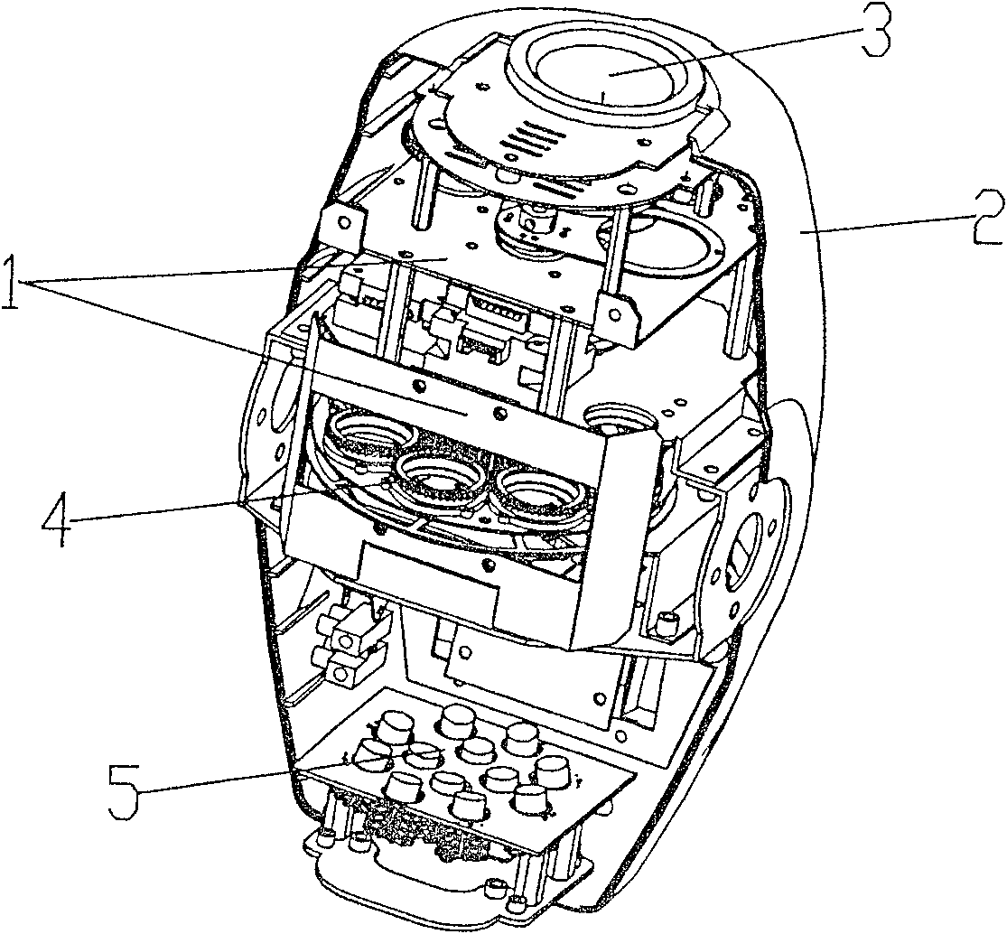
[0029] The LED projection light imaging device of the present invention will be further described below in conjunction with the accompanying drawings:

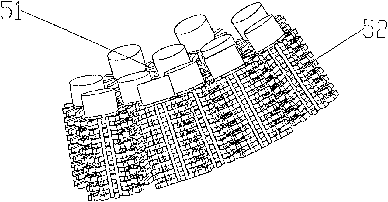
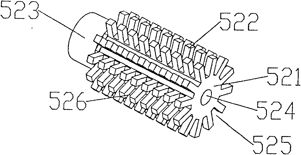
[0030] Such as figure 1 , figure 2 , image 3As shown, the LED projection imaging device of the present invention includes a bracket 1, a housing 2 and an imaging system 3, a rotating disk 4, and a light source 5 arranged in sequence. The imaging system 3 and the rotating disk 4 are installed on the bracket 1. The bead group 52 is arranged according to the shape of the concave surface 51 , and the light-emitting end of each LED lamp bead faces the inner side of the concave surface 51 and points to the focus of the concave surface 51 . The light-emitting end of each LED light bead points to the focus of the concave surface 51 , which means that it is facing the focus or is exactly in focus. The concave surface 51 is a spherical or parabolic curved surface. Each LED lamp bead is provided with a heat dissipation structure, w...


PUM


Abstract

The present invention discloses a LED light-projecting imaging device, which comprises a support, a shell and an imaging system, a rotating disc and a light source which are serially arranged. The imaging system and the rotating disc are arranged on the support. The present invention is characterized in that the light source consists of a LED lamp beads group formed by a plurality of LED lamp beads; each LED lamp bead is distributed on a light concentration concave. The luminescent ends of each LED lamp bead face to the inner side of the concave and point to the focus of the concave. A radiating structure is arranged at the bottom of the LED lamp bead, which consists of a column body and radiation-type strip bodies evenly distributed on the periphery face of the column body. A clearance is arranged between the two neighboring strip bodies placing at the same cycle cross section. The clearance is also arranged between the two neighboring strip bodies along the axis direction of the column body. The axes line of the radiating structure is overlapped with the axes line of a LED illuminant body. Compared with the prior art, the present invention has the advantages of energy-saving, good radiating effect, long service life and dustproof and so on; the present invention can be widely used in the producing of projection lamps and head-shaking lights and so on.

Description

technical field [0001] The invention relates to the field of optoelectronic technology, in particular to an LED light projection imaging device. Background technique [0002] At present, the projection imaging device is generally composed of a bracket, a casing, and an imaging system, a rotating disk, and a light source arranged in sequence. The light source part needs lighting equipment that can emit strong light and concentrate light. Most of the existing equipment uses Common lighting techniques, such as discharge guns. Using a discharge gun as a light source for such equipment has the following disadvantages: [0003] 1. Most of the light emitted by the discharge bulb is infrared (heat), and this heat must be sent away from the optical components, so the optical system must have a cooling system. And this cooling system usually uses a fan, so it cannot be sealed from the outside environment in the optical device, because it needs air inlets and outlets to reduce the he...

Claims


Application Information

Patent Timeline
Patent Type & Authority Patents(China)
IPC IPC(8): G03B21/16H05K7/20F21V29/00F21V29/503F21V29/77
Inventor 陈家强
Owner GUANGZHOU YAJIANG PHOTOELECTRIC EQUIP CO LTD
Why Eureka
Try Eureka