Supercharge Your Innovation With Domain-Expert AI Agents!

Oven system provided with displaceable sluice chamber

A technology of locking chamber and vacuum chamber, which is applied in the field of material furnace system, can solve the problems of increasing investment cost and achieve the effect of reducing the installation length

Inactive Publication Date: 2010-01-13
OTTO JUNKER GMBH
View PDF6 Cites 0 Cited by
  • Summary
  • Abstract
  • Description
  • Claims
  • Application Information

AI Technical Summary

Problems solved by technology

Such a device must be installed in a correspondingly designed machine room, which increases investment costs

Method used


Image

  • Oven system provided with displaceable sluice chamber
  • Oven system provided with displaceable sluice chamber

Examples


Embodiment Construction

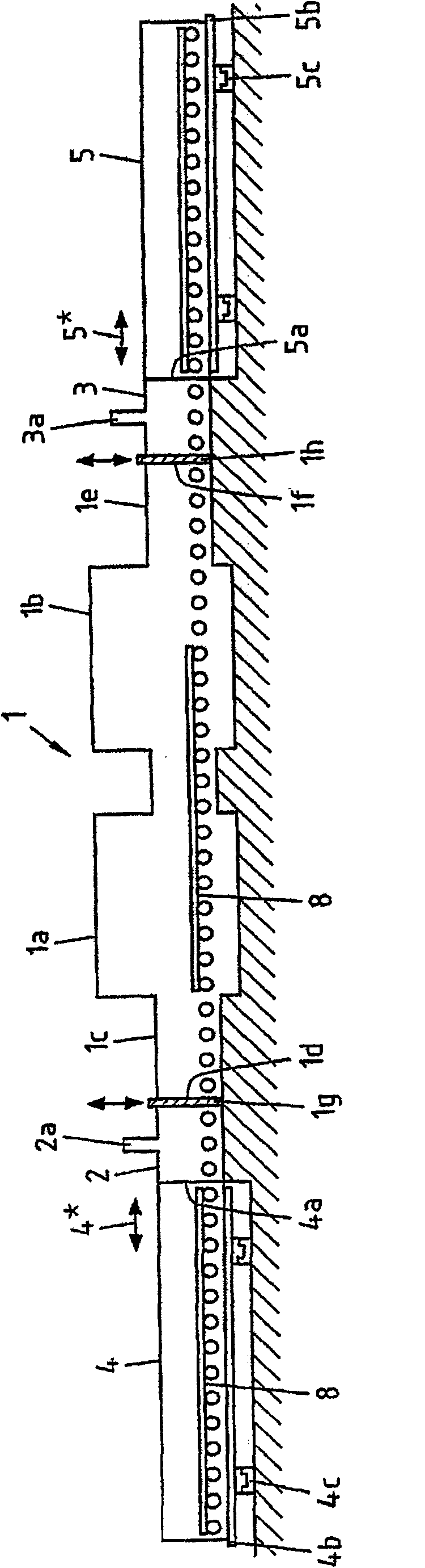
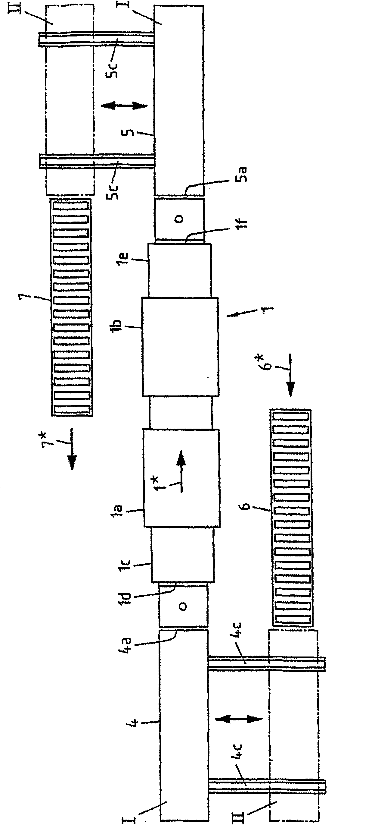
[0014] figure 1 The furnace system in includes a furnace 1 for heat treatment of elongated materials, in particular copper tubes 8, which is symmetrically designed and constructed as a roller hearth furnace and has a heating section 1a and a cooling section 1b. From figure 2 As can be seen in , the copper tube 8 travels through the furnace from left to right, so that the copper tube 8 is first heat treated and then cooled in a controlled manner. Before the heating section 1a, the furnace 1 has an input space 1c with a feed opening 1d, which is preferably closed in an airtight manner with a sliding door 1g. According to the symmetrical structure of the furnace 1, in the direction of travel, after the cooling section 1b, the furnace 1 has an output space 1e with an outlet opening 1f, in the same way as the input space 1c, preferably in an airtight manner with a sliding door 1h To close the discharge port 1f.

[0015] Before the feed opening 1d and after the discharge opening...


PUM


Abstract

The invention relates to an oven system for thermally treating an elongate product, in particular, a roller hearth furnace. Said system comprises a conveying unit which is used to transport the product, an oven comprising a gas-proof, closeable charging door and a sluice chamber which comprises a gas-proof closeable charging door and which is connected to the oven by means of the conveying unit. The sluice receives the product in a charged manner via the charging door and allows it to pass into the oven. The oven system is characterised in that the oven is arranged outside the conveying device of the conveying unit and the sluice chamber can be moved from a first position, wherein it receives the product transported by the conveying unit, to a second position, wherein it is docked, by means of the charging opening, in a gas-proof manner to the charging opening of the oven.

Description

technical field [0001] The present invention relates to a furnace system for the heat treatment of elongated materials, in particular to a roller hearth furnace comprising a delivery unit for feeding the material, comprising a furnace with a gas-tight sealable inlet, and comprising a gas-tight A lock chamber of a hermetically sealed inlet connecting the furnace to the delivery unit, wherein the lock chamber receives and feeds batches of material into the furnace through the inlet. Background technique [0002] In furnace systems known from the prior art, the conveying unit conveying the material to be processed, the lock chamber and the furnace are arranged in one line. Especially when dealing with particularly elongated materials such as steel or copper pipes, enormous installation lengths are reached, since both the furnace itself and the locking chamber arranged in the line must completely receive the elongated material. Such a device has to be installed in a correspondi...

Claims


Application Information

Patent Timeline
Patent Type & Authority Patents(China)
IPC IPC(8): F27B9/26F27B9/30F27B9/38F27D23/00F27D3/00F27D99/00
CPCF27D2099/008F27D99/0073F27D2003/006F27B9/30F27B9/262F27B9/38
Inventor 格林·琼斯维利·约嫩
Owner OTTO JUNKER GMBH
Features
  • R&D
  • Intellectual Property
  • Life Sciences
  • Materials
  • Tech Scout
  • Unparalleled Data Quality
  • Higher Quality Content
  • 60% Fewer Hallucinations
Learn More