Dirty block recovery method for flash memory device

A recycling method and flash memory technology, applied in information storage, static memory, read-only memory, etc., can solve the problem of low overall utilization efficiency of flash memory devices, and achieve the effect of reducing the number of erasing, prolonging the service life, and uniformly erasing

Active Publication Date: 2010-01-13
KONKA GROUP
View PDF3 Cites 0 Cited by
  • Summary
  • Abstract
  • Description
  • Claims
  • Application Information

AI Technical Summary

Problems solved by technology

This leads to inefficient overall utilization of the flash memory device

Method used


Image

  • Dirty block recovery method for flash memory device
  • Dirty block recovery method for flash memory device
  • Dirty block recovery method for flash memory device

Examples


Embodiment Construction

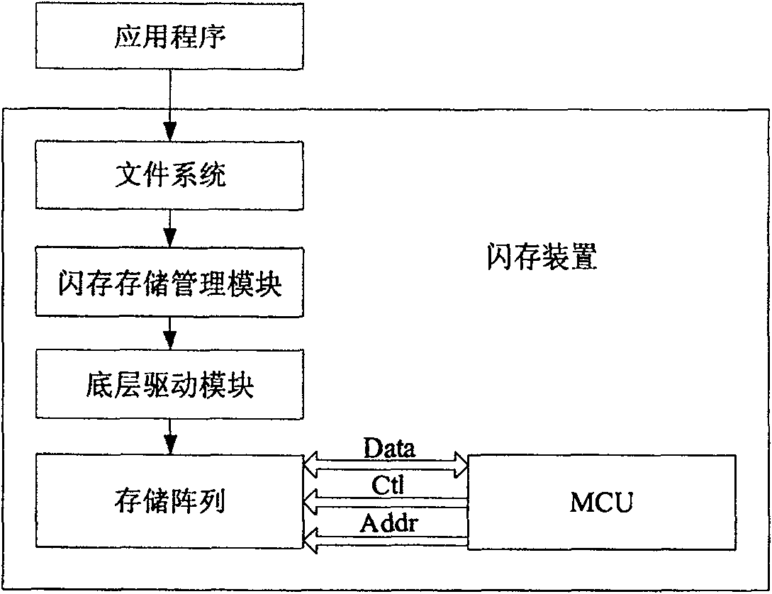
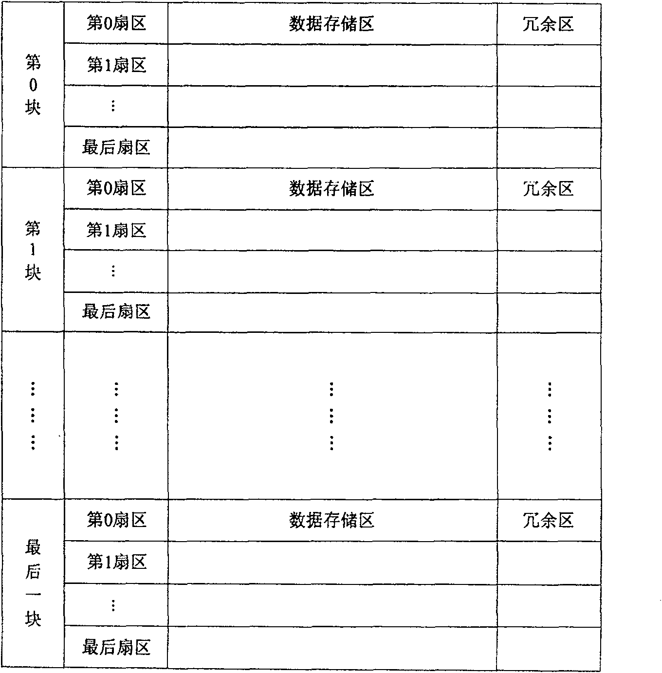
[0031] The flash memory device includes MCU (microcontroller), storage array, bottom drive module, flash storage management module and file system, such as figure 1 As shown, the file system receives external (such as external application) read, write, and erase requests, and reaches the storage array through the flash memory storage management module and the underlying driver module. , write and erase operations. The flash memory storage management module is responsible for balancing the number of erasing and writing between blocks and managing bad blocks. It performs various operations on the storage array through the underlying driver module. The storage array includes multiple blocks, each block is composed of multiple sectors, sometimes called "pages", and each sector is divided into storage area and redundant area, such as figure 2 shown. There is a specific area in each block to store information such as the number of times the block is erased, the status of each sec...


PUM


Abstract

The method includes forced reclaiming step carried out in time of writing sector, and conditional reclaiming step carried out after time of deleting sector. The forced reclaiming step reclaims blocks with most dirty sectors. Conditional reclaiming step is divided into two situations: for reclaiming blocks with number of dirty sectors being reached to a threshold value of dirty sectors; for reclaiming blocks with minimal erasure number. Advantages are: as far as possible to reduce number for erasing blocks, even erasure to make all physical blocks have even service life.

Description

【Technical field】 [0001] The invention relates to the field of semiconductor storage, in particular to a dirty block recovery method of a flash memory device. 【Background technique】 [0002] Flash memory (Flash Memory) has the advantages of high density and good access speed, and is the most widely used storage device in the embedded field, belonging to the EEPROM (Electrically Erasable Programmable Read-Only Memory) type. There are two commonly used flash media, nand flash and nor flash, both of which divide the storage space into erase blocks of a specific size, such as 16KB, 64KB, and so on. They are similar to ordinary SRAM memory in terms of reading, and can generally achieve completely random reading. The biggest difference lies in the writing operation. The writing operation of the Flash memory needs to go through two operation processes of "erase-write". If you want to write to a certain unit, you must first perform an erase operation on the sector (Sector) or bloc...

Claims


Application Information

Patent Timeline
Patent Type & Authority Patents(China)
IPC IPC(8): G11C16/06G11C16/10G11C16/14
Inventor 张建文
Owner KONKA GROUP
Why Eureka
Try Eureka