
Flexible coupling

A coupling and flexible technology, applied in the direction of elastic couplings, couplings, mechanical equipment, etc., can solve the short life of couplings, affect the transmission effect, axial, radial and angular displacement Can not play any compensation role and other problems, to achieve the effect of maintaining the overall performance, improving safety performance, and avoiding the motor from being burned

Active Publication Date: 2010-01-20
黄顺国
View PDF5 Cites 0 Cited by
  • Summary
  • Abstract
  • Description
  • Claims
  • Application Information

AI Technical Summary

Problems solved by technology

[0002] In the prior art, the intermediate coupling of the coupling is generally mainly composed of a cylinder and flanges arranged at both ends of the cylinder, and is made of metal materials, and its structure is generally an integral structure; because the coupling The coupling and its coupling cannot play a good role in damping and absorbing shock vibration when rotating at high speed, thus affecting the transmission effect. Axial, radial and angular displacement can not play any compensation role

Method used


Image

  • Flexible coupling
  • Flexible coupling
  • Flexible coupling

Examples


Embodiment 1

[0032] Example 1: See the accompanying drawings.

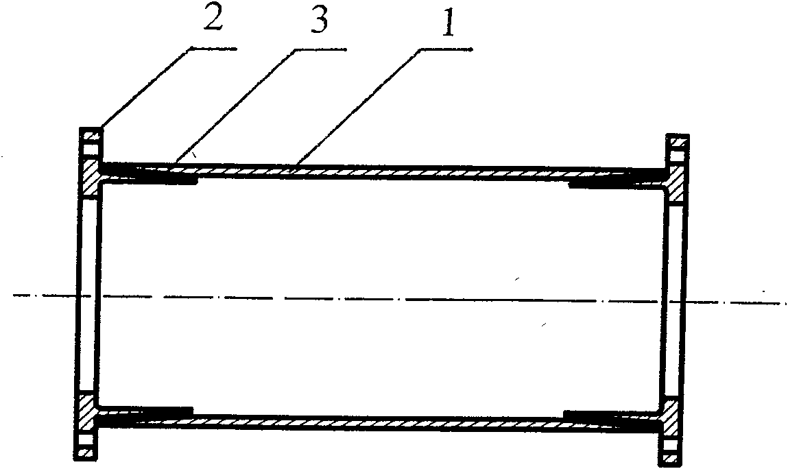
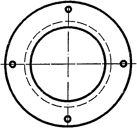
[0033] A flexible coupling, mainly composed of: a glass fiber reinforced plastic cylinder 1 (or FRP cylinder), flanges 2 arranged at both ends of the cylinder, and connected with each flange 2 as a whole (that is, integrally formed) Taper sleeve 3 (flange 2 and taper sleeve 3 can be cast iron or other metal materials);

[0034] The two ends of the FRP cylinder 1 are respectively socketed and fixedly bonded to a taper sleeve 3. The adhesive can be a two-component methacrylic structural adhesive (for example: Plexus MA310, etc.), or an existing Other adhesives in technology;

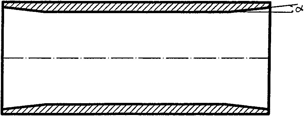
[0035] The inner surfaces of both ends of the FRP cylinder 1 are socketed with the taper sleeve 3, and the angle α between the FRP cylinder 1 and the central axis is 4 degrees, and the taper of the taper sleeve 3 corresponds to the angle α. , is 4 degrees;

[0036] The FRP cylinder 1 is composed of multiple glass fiber layers bonded by resin;

[0037] ...

Embodiment 2

[0043] Embodiment 2: refer to each accompanying drawing.

[0044] A flexible coupling, the inner surface of both ends of the glass fiber reinforced plastic cylinder 1 is socketed with the taper sleeve 3, the angle α between the glass fiber reinforced plastic cylinder 1 and the central axis is 1 degree, and the taper of the tapered sleeve 3 is in line with the The included angle α corresponds to the same, being 1 degree; others are the same as in Embodiment 1, omitted.

Embodiment 3

[0045] Embodiment 3: refer to each accompanying drawing.

[0046]A flexible coupling, the inner surfaces of both ends of the glass fiber reinforced plastic cylinder 1 are sleeved with the taper sleeve 3, the angle α between the glass fiber reinforced plastic cylinder 1 and the central axis of the sleeve is 5 degrees, and the taper of the taper sleeve 3 is equal to The included angle α corresponds to the same, which is 5 degrees;


PUM


Abstract

The invention provides a flexible coupling, comprising a cylinder body and flanges which are arranged at two ends of the cylinder body. The invention is characterized in that the cylinder body is an FRP cylinder body; the flanges are fixedly connected with or integrated into a whole with a taper sleeve or a cylinder sleeve; the two ends of the FRP cylinder body are sheathed with, fixedly bonded to or fixedly connected with the taper sleeve or the cylinder sleeve respectively. The invention is especially suitable for the connection of a speed increasing box in wind power generation equipment and a wind power generation set, plays a good damping and impact and vibration absorption role, has the capability of providing the displacement compensation, effectively improves the motion quality and stability of transmission machines, reduces the noise and improves the safety performance of the equipment.

Description

technical field [0001] The invention relates to a component of a coupling that transmits rotational motion—an intermediate coupling of a high-speed flexible coupling, in particular to a flexible coupling. It is suitable for the connection device between the gearbox and the wind power generating set (especially the wind power generating equipment above 1.5 MW) in the wind power generation equipment, and can also be used as the power transmission device of other equipment. technical background [0002] In the prior art, the intermediate coupling of the coupling is generally mainly composed of a cylinder and flanges arranged at both ends of the cylinder, and is made of metal materials, and its structure is generally an integral structure; because the coupling The coupling and its coupling cannot play a good role in damping and absorbing shock vibration when rotating at high speed, thus affecting the transmission effect. Axial, radial and angular displacements cannot play any c...

Claims


Application Information

Patent Timeline
Patent Type & Authority Patents(China)
IPC IPC(8): F16D3/74
Inventor 黄顺国
Owner 黄顺国
Learn More