Supercharge Your Innovation With Domain-Expert AI Agents!

Rotary squeezing filling pile and pile-forming method therefor

A cast-in-situ pile and pile-forming technology, which is applied to sheet pile walls, foundation structure engineering, construction, etc., can solve problems affecting construction speed, environmental pollution, noise pollution, etc., and achieve reliable hole quality

Active Publication Date: 2010-01-27
HAINAN ZHUODIAN HIGH TECH DEV
View PDF10 Cites 0 Cited by
  • Summary
  • Abstract
  • Description
  • Claims
  • Application Information

AI Technical Summary

Problems solved by technology

[0004] A. Using the hopper-type pouring method, continuous pouring of concrete into piles cannot be realized;
[0005] B. Using the method of directly lifting steel pipes to pour concrete, human factors cause frequent pile breakage, diameter shrinkage, and mud inclusions
[0006] ② Serious noise pollution and extremely slow construction speed have attracted increasing attention from the society. Construction limitations and construction costs restrict the development of cast-in-place piles and their construction methods
[0009] B. Environmental pollution caused by soil extraction for construction is increasingly restricted by the social environment;
[0010] C. The construction site caused by soil borrowing seriously affects the construction speed
[0011] 3. Patent No.: ZL03128265.2 The semi-screw pile and its construction method obviously overcome the defects of the above piles and its construction method, but this method cannot be applied because the cross-sectional area of ​​the horizontal pile core in the lower part of the pile is smaller than the upper straight section In the range of end-bearing piles

Method used


Image

  • Rotary squeezing filling pile and pile-forming method therefor
  • Rotary squeezing filling pile and pile-forming method therefor
  • Rotary squeezing filling pile and pile-forming method therefor

Examples


Embodiment Construction

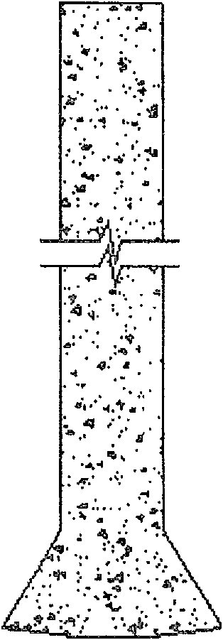
[0047] One-time rotary extrusion grouting pile consists of two parts, such as figure 1 As shown, the upper part of the pile is a linear cylinder with equal diameter, and the lower part of the pile is an enlarged head vertebral body, and the diameter of the enlarged head vertebral body is between 1.0-2.0 times the diameter of the cylinder.

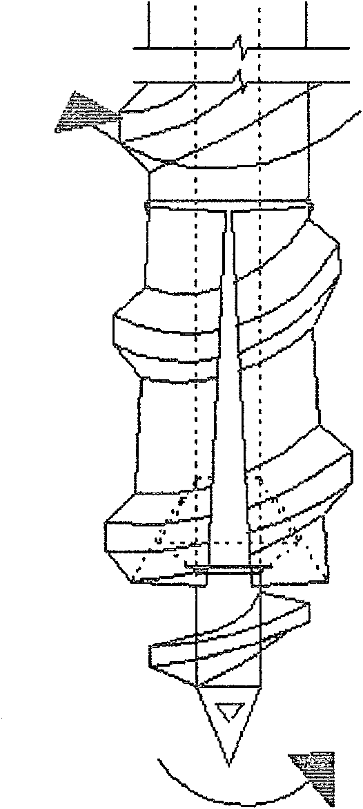
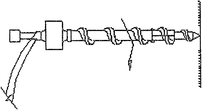
[0048] Depending on the stratum, the diameter can also be kept constant, and the pile-forming equipment described in Patent Application No. 200610019756.6 is adopted, and the drilling rig of the pile-forming equipment is changed into a pile construction method for one-time pile-forming construction. The specific steps are as follows:

[0049] 1. Use the pile-forming equipment described in the patent application number: 200610019756.6 to carry out the pile-forming method according to the following steps: Step 1: Use the pile-forming equipment described in the application number: 200610019756.6 to align the pile position, and the longitudinal ...


PUM


Abstract

The invention relates to a rotating compression pile-pouring and a pile-forming method, wherein the rotating compression pouring pile consists of two portions, and an upper portion is a rectilinear equal diameter cylinder, while a lower portion is an enlarged footing cone whose diameter is between one to double of the cylinder diameter. The pile-forming method is that a drill rod and a drill machine of the pile-forming device compress the soil to a straight rod nut soil in the range of pile length firstly, and a tensioner of the pile-forming device is provided to a enlarged footing soil, and then a pump pressure concrete pumps the concrete via a core bottom of the drill rod, while the drill rod is rotated and lifted simultaneously, and the enlarged footing and the tensioner are returned to the original position, while the filling pile is rotary compressed by the pump pressure concrete in full range. The invention has advantages that a pore-forming compressed by drills rotary compression has reliable quality with no noise and borrowing, and the pile has the same diameter and the enlarged footing in its lower end, therefore the bearing ability of the invention is far better than that of the filling pile with sink-tubes and common drill holes.

Description

technical field [0001] The invention relates to an engineering rotating extruded cast-in-place pile and a pile forming method thereof in the construction field. technical background [0002] 1. The traditional immersed tube cast-in-situ pile and its pile-forming method are increasingly exposing the following shortcomings: [0003] ① The quality of the pile body is obviously discrete, which is mainly restricted by the following construction conditions: [0004] A. Using the hopper-type pouring method, continuous pouring of concrete into piles cannot be realized; [0005] B. Using the direct lifting steel pipe pouring concrete method, human factors lead to frequent pile breakage, diameter shrinkage, and mud inclusions. [0006] ② Serious noise pollution and extremely slow construction speed have attracted increasing attention from the society. Construction limitations and construction costs restrict the development of cast-in-place piles and their construction methods. [0...

Claims


Application Information

Patent Timeline
Patent Type & Authority Patents(China)
IPC IPC(8): E02D5/36
Inventor 彭桂皎彭樱谭燕姬
Owner HAINAN ZHUODIAN HIGH TECH DEV
Features
  • R&D
  • Intellectual Property
  • Life Sciences
  • Materials
  • Tech Scout
  • Unparalleled Data Quality
  • Higher Quality Content
  • 60% Fewer Hallucinations
Learn More